


ASUS P4V533-MX motherboard user guide
1-17
1.12 Connectors
This section describes and illustrates the internal connectors on the motherboard.
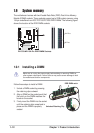
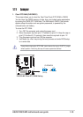
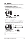
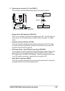
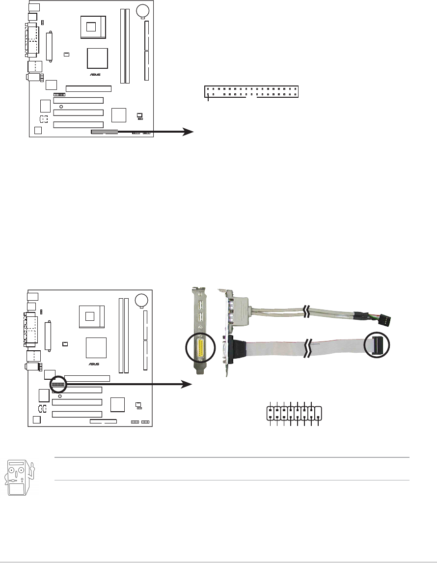
1. Floppy disk drive connector (34-1 pin FLOPPY1)
This connector supports the provided floppy drive ribbon cable. After
connecting one end to the motherboard, connect the other end to the floppy
drive. (Pin 5 is removed to prevent incorrect insertion when using ribbon cables
with pin 5 plug).
P4V533-MX
®
NOTE: Orient the red markings o
n
the floppy ribbon cable to PIN 1.
P4V533-MX Floppy Disk Drive Connector
PIN 1
FLOPPY1
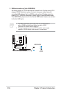
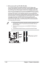
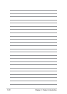
2. GAME/MIDI connector (16-1 pin GAME1)
This connector supports a GAME/MIDI module. Connect the GAME/MIDI cable
with yellow connector to the yellow header onboard. The GAME/MIDI port on
the module connects a joystick or a game pad for playing games, and MIDI
devices for playing or editing audio files.
The GAME/MIDI module is purchased separately.
P4V533-MX
®
P4V533-MX Game/MIDI connector
GAME1
+5V
+5V
J2B1
J2CX
MIDI_OUT
J2CY
J2B2
MIDI_IN
J1B1
J1CX
GND
GND
J1CY
J1B2
+5V