


28 ASUS P5A User’s Manual
III. INSTALLATION
Connectors
III. INST ALLATION
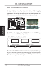
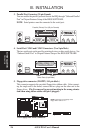
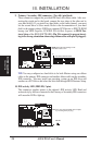
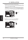
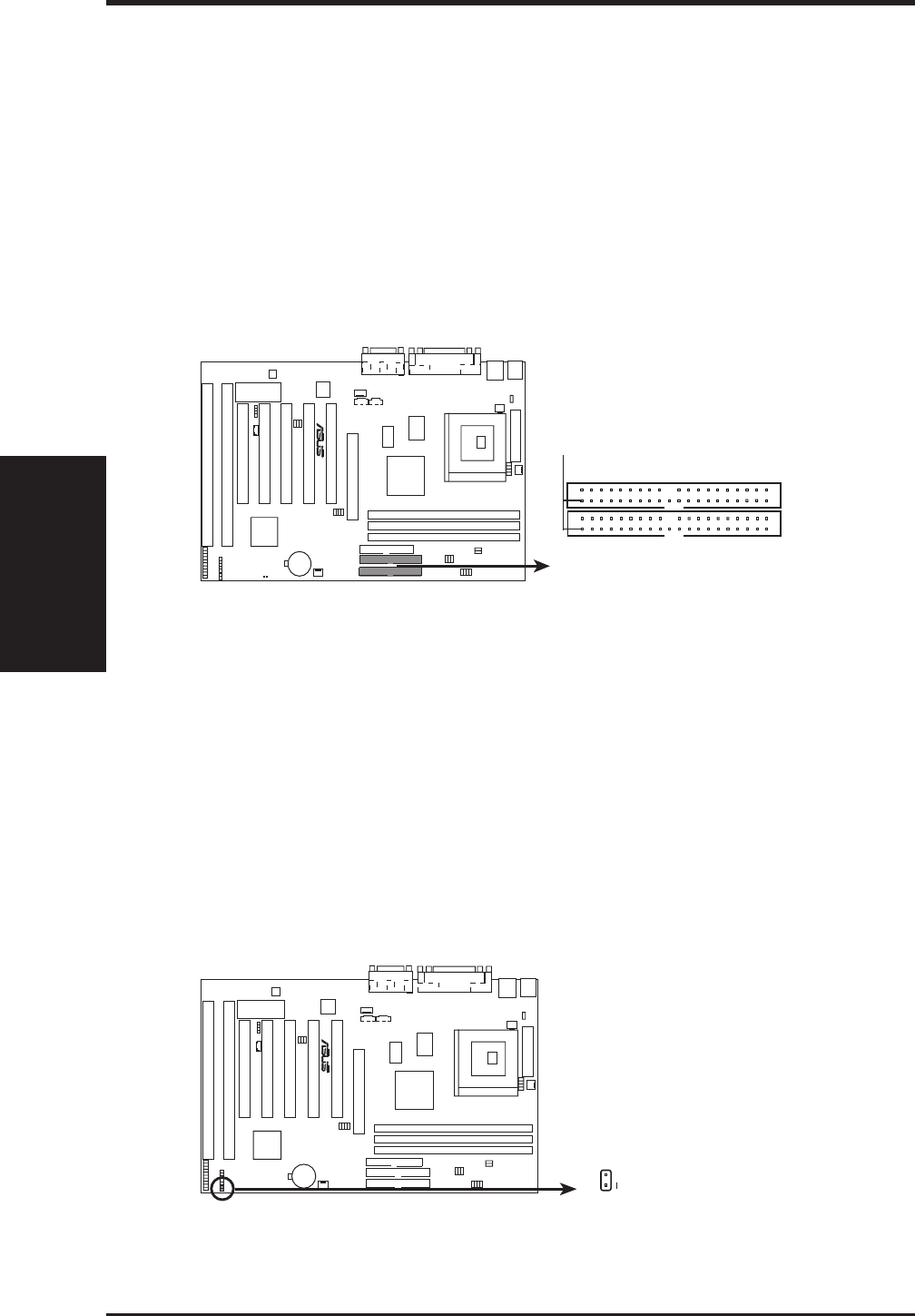
9. Primary / Secondary IDE connectors (Two 40-1 pin block)
These connectors support the provided IDE hard disk ribbon cable. After con-
necting the single end to the board, connect the two plugs at the other end to
your hard disk(s). If you install two hard disks on the same channel, you must
set the second drive to Slave mode. Refer to the documentation of your hard
disk for the jumper settings. BIOS now supports SCSI device or IDE CD-ROM
bootup (see HDD Sequence SCSI/IDE First & Boot Sequence in BIOS Fea-
tures Setup of the BIOS SOFTWARE) (Pin 20 is removed to prevent insert-
ing in the wrong orientation when using ribbon cables with pin 20 plugged).
R
Primary IDE Connector
PIN 1
Secondary IDE Connector
P5A IDE Connectors
NOTE: Orient the red markings on the
IDE ribbon cable to
PIN 1
TIP: You may configure two hard disks to be both Masters using one ribbon
cable on the primary IDE connector and another ribbon cable on the secondary
IDE connector. You may install one operating system on an IDE drive and
another on a SCSI drive and select the boot disk through BIOS Features Setup.
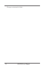
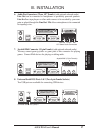
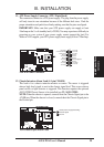
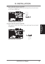
10. IDE activity LED (IDELED, 2 pins)
This connector supplies power to the cabinet’s IDE activity LED. Read and
write activity by devices connected to the Primary or Secondary IDE connectors
will cause the LED to light up.
P5A IDE Activity LED
TIP: If the case-mounted LED does not light,
try reversing the 2-pin plug.
IDELED
+
R