


2-18
Chapter 2: Hardware information
Chapter 2
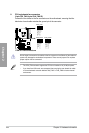
Never connect a 1394 cable to the USB connectors. Doing so will damage the motherboard!
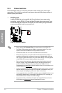
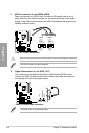
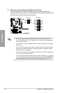
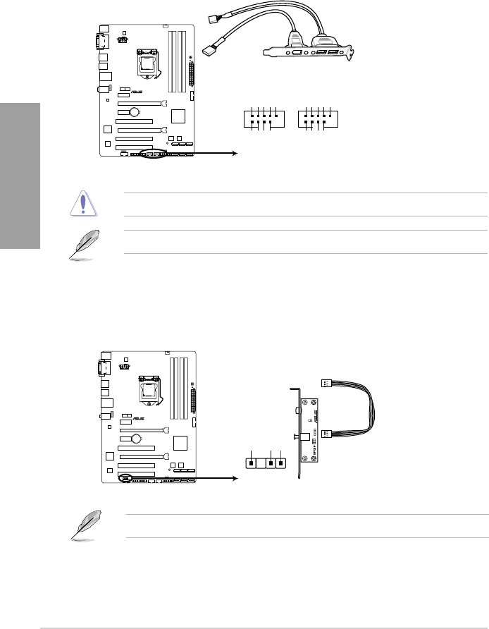
5. USB 2.0 connectors (10-1 pin USB56, USB78)
These connectors are for USB 2.0 ports. Connect the USB module cable to any of
these connectors, then install the module to a slot opening at the back of the system
chassis. These USB connectors comply with USB 2.0 specication that supports up to
48 MBps connection speed.
The USB 2.0 module is purchased separately.
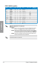
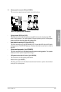
P8B75-V
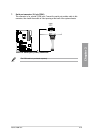
P8B75-V USB2.0 connectors
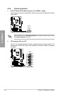
USB+5V
USB_P8-
USB_P8+
GND
NC
USB+5V
USB_P7-
USB_P7+
GND
USB78
PIN 1
USB+5V
USB_P6-
USB_P6+
GND
NC
USB+5V
USB_P5-
USB_P5+
GND
USB56
PIN 1
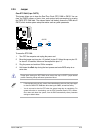
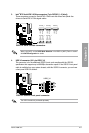
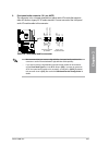
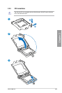
6. Digital audio connector (4-1 pin SPDIF_OUT)
This connector is for an additional Sony/Philips Digital Interface (S/PDIF) port(s).
Connect the S/PDIF Out module cable to this connector, then install the module to a
slot opening at the back of the system chassis.
The S/PDIF module is purchased separately.
SPDIF_OUT
+5V
SPDIFOUT
GND
P8B75-V
P8B75-V Digital audio connector