


1-21 Chapter 1: Product introduction
Never connect a 1394 cable to the USB connector. Doing so will damage the motherboard!
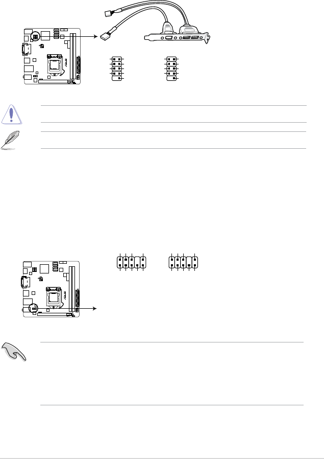
The USB module cable is purchased separately.
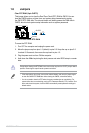
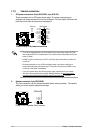
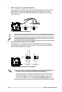
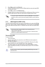
7. USB 2.0 connector (10-1 pin USB78, USB56)
This connector is for a USB 2.0 port. Connect the USB module cable to this connector,
then install the module to a slot opening at the back of the system chassis. This
USB connector complies with USB 2.0 specications and supports up to 480 Mbps
connection speed.
P8H61-I R2.0
P8H61-I R2.0 USB2.0 connectors
PIN 1
USB+5V
USB_P8-
USB_P8+
GND
NC
USB+5V
USB_P7-
USB_P7+
GND
USB78
PIN 1
USB+5V
USB_P6-
USB_P6+
GND
NC
USB+5V
USB_P5-
USB_P5+
GND
USB56
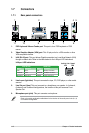
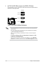
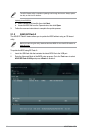
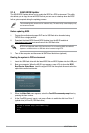
8. Front panel audio connector (10-1 pin AAFP)
This connector is for a chassis-mounted front panel audio I/O module that supports
either HD Audio or legacy AC`97 audio standard. Connect one end of the front panel
audio I/O module cable to this connector.
• We recommend that you connect a high-denition front panel audio module to this
connector to avail of the motherboard’s high-denition audio capability.
• If you want to connect a high-denition front panel audio module to this connector, set
the Front Panel Type item in the BIOS setup to [HD]. If you want to connect an AC'97
front panel audio module to this connector, set the item to [AC97]. By default, this
connector is set to [HD]. See section 2.5.6 Onboard Devices Conguration for details.
P8H61-I R2.0
P8H61-I R2.0 Front panel audio connector
AAFP
AGND
NC
SENSE1_RETUR
SENSE2_RETUR
PORT1 L
PORT1 R
PORT2 R
SENSE_SEND
PORT2 L
HD-audio-compliant
pin definition
PIN 1
AGND
NC
NC
NC
MIC2
MICPWR
Line out_R
NC
Line out_L
Legacy AC’97
compliant definition