


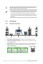
1-26 Chapter 1: Product introduction
Do not forget to connect the fan cables to the fan connectors. Insufcient air ow inside the
system may damage the motherboard components. These are not jumpers! Do not place
jumper caps on the fan connectors!
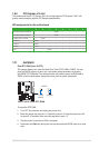
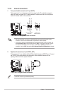
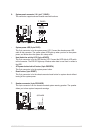
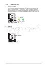
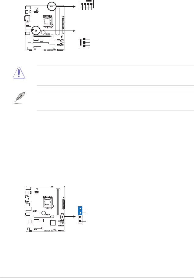
4. CPU and chassis fan connectors (4-pin CPU_FAN, 3-pin CHA_FAN)
Connect the fan cables to the fan connectors on the motherboard, ensuring that the
black wire of each cable matches the ground pin of the connector.
• The CPU_FAN connector supports a CPU fan of maximum 2A (24 W) fan power.
• Only the 4-pin CPU fan supports the ASUS Q-Fan 2 feature.
CHA_FAN
P8H77-M LE
P8H77-M LE fan connectors
GND
+12V
Rotation
CPU_FAN
CPU FAN PWM
CPU FAN IN
CPU FAN PWR
GND
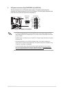
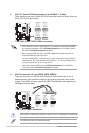
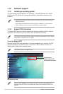
5. Chassis intrusion connector (4-1 pin CHASSIS)
This connector is for a chassis-mounted intrusion detection sensor or switch. Connect
one end of the chassis intrusion sensor or switch cable to this connector. The chassis
intrusion sensor or switch sends a high-level signal to this connector when a chassis
component is removed or replaced. The signal is then generated as a chassis intrusion
event.
By default, the pin labeled “Chassis Signal” and “Ground” are shorted with a jumper
cap. Remove the jumper caps only when you intend to use the chassis intrusion
detection feature.
CHASSIS
GND
Chassis Signal
+5VSB_MB
P8H77-M LE
P8H77-M LE Chassis intrusion connector