


4-5ASUS T3-P5G965
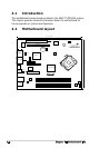
4.4 Connectors
This section describes and illustrates the connectors on the motherboard.
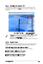
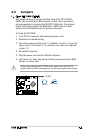
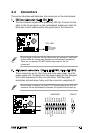
1. CPU fan connector (4-pin CPU_FAN)
The fan connector supports the proprietary CPU fan. Connect the fan
cable to the fan connector on the motherboard, making sure that the
black wire of each cable matches the ground pin of the connector.
Do not forget to connect the fan cable to the fan connector. Insufcient
air ow within the system may damage the motherboard components.
These are not jumpers! DO NOT place jumper caps on the fan
connectors!
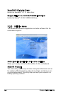
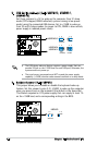
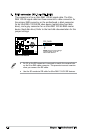
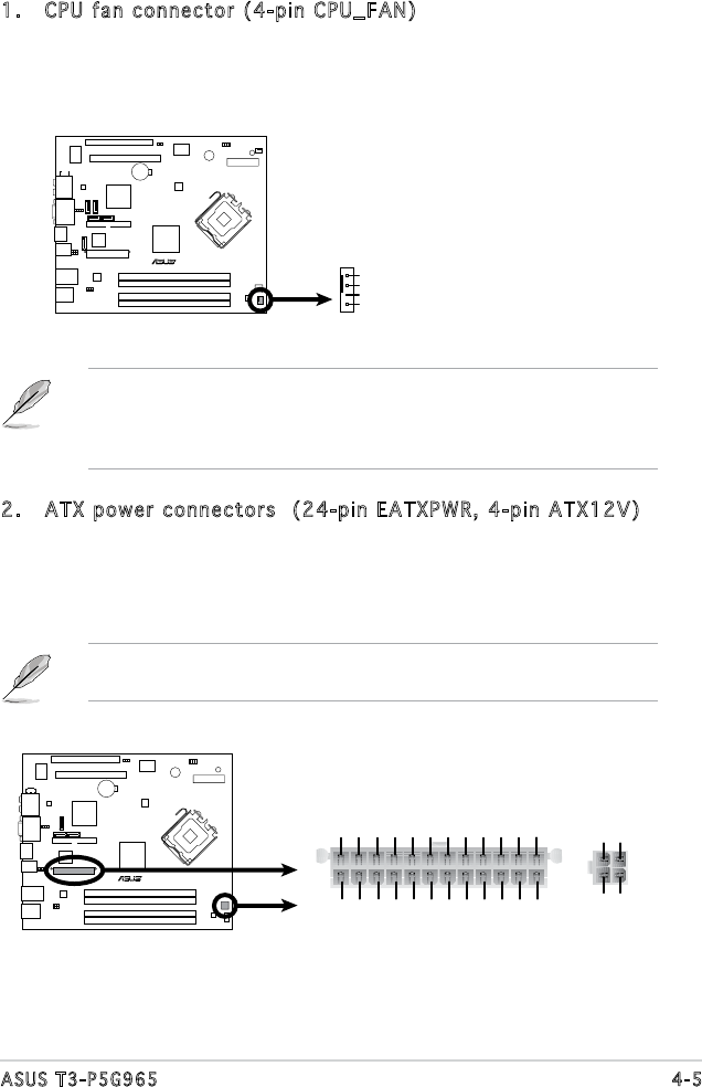
2. ATX power connectors (24-pin EATXPWR, 4-pin ATX12V)
These connectors are for the 24-pin and 4-pin power plugs from the
power supply unit. The plugs from the power supply unit are designed
to t these connectors in only one orientation. Find the proper
orientation and push down rmly until the connectors completely t.
Do not forget to connect the 4-pin ATX12V power plug to the ATX12V
connector on the motherboard; otherwise, the system will not boot up.
R
CPU Fan Connector
CPU_FAN
GND
CPU FAN PWR
CPU FAN IN
CPU FAN PWM
R
ATX Power Connector
EATXPWR
+3 Volts
+3 Volts
Ground
+5 Volts
+5 Volts
Ground
Ground
Power OK
+5V Standby
+12 Volts
-5 Volts
+5 Volts
+3 Volts
-12 Volts
Ground
Ground
Ground
PSON#
Ground
+5 Volts
+12 Volts
+3 Volts
+5 Volts
Ground
ATX12
V
GND
+12V DC
GND
+12V DC