


1-7ASUS Vintage V2-PE2
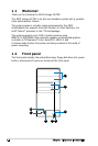
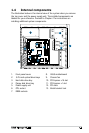
1.4 Internal components
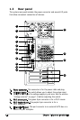
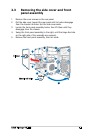
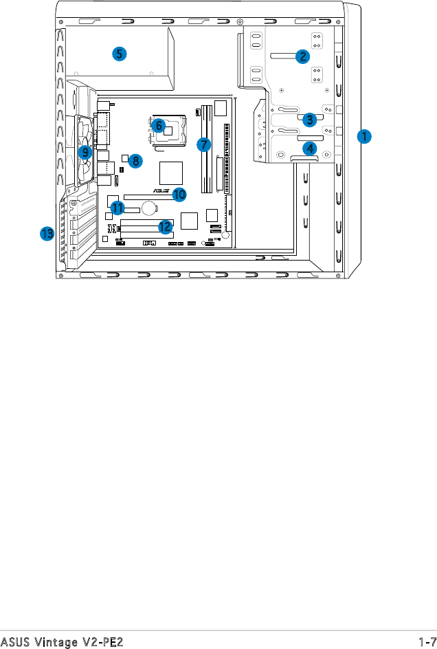
The illustration below is the internal view of the system when you remove
the top cover and the power supply unit. The installed components are
labeled for your reference. Proceed to Chapter 2 for instructions on
installing additional system components.
1. Front panel cover
2. 5.25-inch optical drive bays
3. Hard disk drive bay
4. Floppy disk drive bay
5. Power supply unit
6. CPU socket
7. DIMM sockets
8. ASUS motherboard
9. Chassis fan
10. PCI Express x16 slot
11. PCI Express x1 slot
12. PCI slots
13. Metal bracket lock
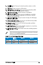
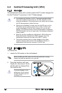
LGA775
DDR2 DIMM1 (128 bit,240-pin module)
DDR2 DIMM2 (128 bit,240-pin module)
VIA
P4M890
VIA
8237A
4Mb
BIOS
PCIEX16
PCIEX1
PCI1
PCI2
CR2032 3V
Lithium Cell
CMOS Power
SEC_IDE
PRI_IDE
FLOPPY
SATA2
SATA1
CD AUX
AAFP
USB56
USB78
CHA_FAN
CPU_FAN
Super I/O
EATXPWR
ATX12V
SATA_A
BUZZER
CLRTC
CHASSIS
USBPW56
USBPW78
USBPW56
USBPW78
SPDIF_OUT
KBPWR
SB_PWR
F_PANEL
ADI1986A
RTL8201CL
JMB363
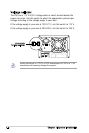
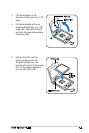
Below:Mic In
Center:Line Out
Top:Line In
USB12
RJ-45
Top:
USB3
USB4
Bottom:
R
PS/2KBMS
T: Mouse
B: Keyboard
VGA
ESATA
PARALLEL PORT
21.8cm (8.6in)
24.5cm (9.6in)
COM2
6
1
2
3
4
13
11
9
7
8
5
12
10