


ENGLISH
A05-17AM-D01 - A05-17BM-D03 - A05-19BM-D02_X02 9 - 40
4.6.2 Recall the factory default setting
4.6.3 Sharpness
Adjust the picture display more clear
Exit Close the Tools OSD menu
Exit Close the OSD menu
5 Micro-controller Features
The micro-controller automatically detects the video board installed in your system. When you turn on the
monitor, the micro-controller first checks the display mode memory stored in the user setting area of the
video board, and then the factory presetting area. It then adjusts to the proper display mode.
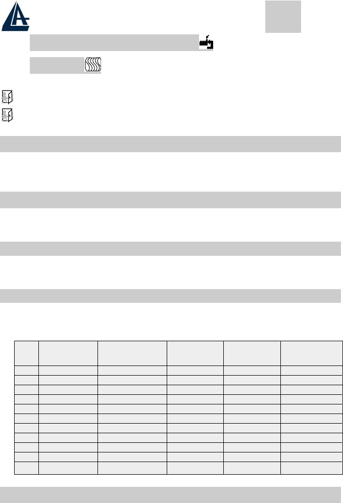
6 Display Modes Memory
The micro-controller has the memory capacity to store different display modes, including timing formats and
display-settings. This memory capacity is divided into two parts: the user setting area and the factory
presetting area.
6.1 User Setting Area
The user setting area on the micro-controller maintains in its memory the last display modes set by the
user. You can change the settings, or add a nonstandard mode. The micro-controller always detects and
displays the last mode stored in the user setting area first when the monitor is turned on.
6.2 Factory Presetting Area
There are some preferred display modes preset in the micro-controller. These display modes are preset
at the factory and include the most popular display modes currently available. The micro-controller
searches for a proper display mode in this area if it fails to find a proper display mode in the user setting
area.
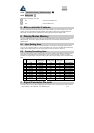
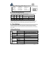
MODE
Resolution
(Dots*lines)
Horizontal
Freq. (KHz)
Vertical
Freq. (Hz)
Remark
1. VGA 640×350 31.5 70 Non-interlaced
2. VGA 720×400 31.5 70 Non-interlaced
3. VGA 640×480 31.5 60 Non-interlaced
4. VESA/75 640×480 37.5 75 Non-interlaced
5. VESA/60 800×600 37.9 60 Non-interlaced
6. VESA/75 800×600 46.9 75 Non-interlaced
7. VESA/60 1024×768 48.4 60 Non-interlaced
8. VESA/70 1024×768 56.5 70 Non-interlaced
9. VESA/75 1024×768 60.0 75 Non-interlaced
10. VESA/60 1280×1024 64.0 60 Non-interlaced
11. VESA/75 1280×1024 80.0 75 Non-interlaced
7 Signal Connector Pin-outs
To connect VGA, 8514A or IBM-compatible graphics adapters, use a 15 pin mini D-type male connector.