


AVR2070
43
8240B-AVR-06/09
Appendix B - Firmware API Overview
This appendix discusses how the RUM firmware is implemented, what Application
Programming Interface (API) functions are present, and gives some detail about what
functions are called to implement the RUM protocol.
The firmware source, available with this Application Note, has been extensively
documented in source code comments. This documentation exists as HTML pages
which are generated from the source itself using the Doxygen program. Refer to the
Doxygen-generated documentation for a more detailed description of how the
firmware operates and complete list of API and functions.
The descriptions of software organization in this appendix apply to the AVR version of
the firmware. The SAM-7X version firmware uses a multitasking OS – µTasker – to
coordinate the various tasks, but the flowcharts below still largely apply.
B.1 Program Organization
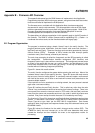
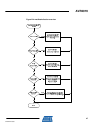
The program is structured using a simple “forever” loop in the main() function. The
program performs some initialization, and then forever calls some task functions –
appTask() and macTask(). These two functions service events generated by interrupt
service routines (ISR’s). Examples of ISR’s include the radio interrupt (packet
received or sent), timer interrupt, and serial port interrupt.
The main loop processing is called the foreground, and the ISR processing is called
the background. Communication between background (ISR functions) and
foreground (main loop) is done with an event queue. The background process stores
an event in the queue with the mac_put_event() function, and the foreground pulls
events from the queue with a call to mac_get_event(). In this way ISR events can be
handled without clobbering foreground processing.
Figure B-1 shows this overall scheme.
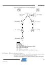
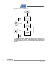
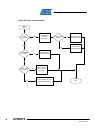
The main() function configures the system before entering the main loop. Most of the
hardware setup is done in the appInit() function. Figure B-2 shows the major events
that occur as a result of calling appInit. A coordinator node will create a new network
with itself at the center, and a router or end node will connect itself (associate) to the
closest available network.
If the node fails to find or associate to an existing network, the scan process is started
again after a one second delay.
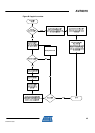
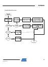
Figure B-3 outlines the macTask() function. This is called very often from the main
“forever” loop, and handles events that have arise from interrupt routines. There is an
event queue that stores the interrupt events in FIFO order, and macTask() retrieves
items from the queue and processes each one in the order in which the events were
received. Every event except for serial character I/O is handled by macTask().
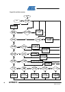
The flowchart in Figure B-4 shows how macDataIndication() dispatches received data
frames. A “data frame” here means a frame with the Frame Control Field element
Frame Type set to type “data” per the IEEE 802.15.4 specification. Data frames
application data, ping request and response frames, drop child command frames, and
6LoWPAN frames.
Figure B-6 shows the flowchart for the radio’s interrupt service routine (ISR). The
AT86RF2xx family has one interrupt pin, so the ISR must determine what event
caused the interrupt and then dispatch the event to the appropriate routine for
processing.