


Hardware Description
2-7 C51 Microcontrollers Demo Board User Guide
4119C–8051–3/03
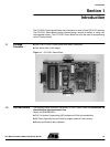
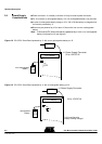
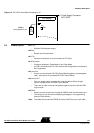
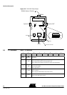
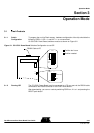
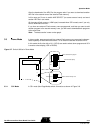
Figure 2-5. C51/C251 Demo Board
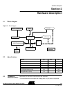
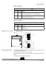
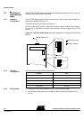
2.6 J11 Switches Table 1. J11 Switches
(Set=1, Clear=0)
J11
J9
J16
RS232 Cable to Terminal
J8
J8
LCD CTRST
+
RESET
INT1
OFF
ON
J17
R21
Page Mode
Non Page Mode
Synchro IN
Synchro OUT
RS232
LCD
11
1
X2
X3
X1
PLCC44
PLCC68
DIL24
Extension connector
76543210
ISP ALE PSEN UC4 UC3 UC2 UC1 UC0
Bit
Number
Bit
Mnemonic Description
7ISP1
In-System Programming (external Flash memory)
Set to enable external Flash memory programming
Clear to protect external Flash memory from erasure and programming
6ALE
Address Latch Enable
Set to see ALE activity
Clear to ground ALE
5PSEN
Program Store Enable
Set to run demos
Clear to program T89C51RD2 on-chip Flash memory
4-0 UC4:0
User Code
Free of use as data input for demos.