


Operation Mode
C51 Microcontrollers Demo Board User Guide 3-10
4119C–8051–3/03
Section 3
Operation Mode
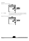
3.1 Flash Products
3.1.1 Switch
Configuration
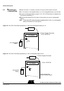
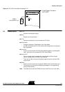
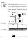
To program the on-chip Flash memory, hardware configuration of the chip should be the
following: PSEN = 0, EA = 1 and ALE = 1 or not connected.
On C51/C251 Demo Board, switches must be as shown on Figure 3-2.
Figure 3-1. C51/C251 Demo Board Switches Configuration to use ISP
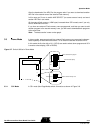
3.1.2 Running ISP The C51/C251 Demo Board must be connected to a PC com port via the RS232 cable
connected to the RS232 connector of C51/C251 Demo Board.
After downloading, you can run code by switching PSEN on J11 to 1 and pressing the
RESET push button.
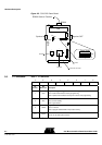
J11
PSEN
ALE
ISP1
User Code
1
0
10
J11
J9
J16
J9
J16
EA
MAP SELECT
ISP2
RS232 Cable to PC
Position don’t care
Position needed