


ATTO Technology, Inc. ATTO FibreBridge Installation & Operation Manual
- 19 -
ATTO Technology, Inc.
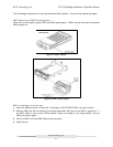
possible to connect slower “Legacy” devices of one SCSI bus of the bridge while connecting faster
devices on the second. Each bus can communicate at independent rates.
The ATTO FibreBridge supports a wide variety of SCSI storage devices including stand-alone drives,
removable drives, JBODs, RAIDs, Tape, CD and DVD drives, changers, libraries, magneto optical drives,
Jaz and Zip devices.
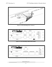
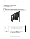
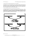
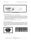
LED Indicators
Figure 5.7 LED Indicators on FibreBridge 2200R/D
Power– There is an LED to indicate if power is available from the supply.
FC Activity – This LED blinks to show activity occurring on the Fibre Channel port of the unit. This may
appear to be steadily lit during times of very high activity.
SCSI 1 Activity, SCSI 2 Activity – There is one LED for each SCSI bus that displays activity on the SCSI
bus.
Ready – A few seconds after power has been applied, the Ready LED should be illuminated. This
indicates that the FibreBridge has passed its power on self-test and is now ready for normal operation.
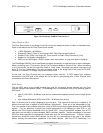
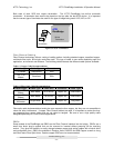
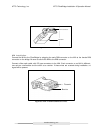
Ethernet Port
The 10/100 BaseT Ethernet port provides SNMP and Telnet based monitoring and management through
a command line interface, menu system or graphical interface (BridgeTools). Refer to the FibreBridge
Software manual and the BridgeTools manual for details on the available commands for communication
with the bridge.
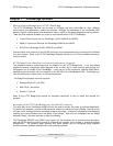
Serial Port
The RS-232 serial port provides support for remote monitoring and management through a command line
interface, menu system or graphical interface (BridgeTools). Refer to the FibreBridge Software manual
and the BridgeTools manual for details on the available commands for communication with the bridge.