


Power up
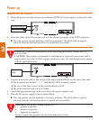
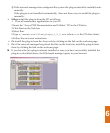
Avaya P330 AC Version
1. Insert the power cord into the power connector (BUPS or Power Supply) on the rear of the
unit.
2. Insert the other end of the power cord into the electricity supply or the BUPS connector.
! The unit powers up and performs a self test procedure. The LEDs flash at regular
intervals after the self-test procedure is completed successfully.
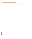
Avaya P330 DC Version
WARNING: Before performing any of the following procedures, ensure that DC
power is OFF.
CAUTION: This product is intended for installation in restricted access areas and is
approved for use with 18 AWG copper conductors only. The installation must comply
with all applicable codes.
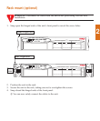
1. Connect the power cable to the switch at the input terminal block on the rear of the unit.
! The terminals are marked “+”, “-“ and the IEC 5019a Ground symbol.
! The size of the three screws in the terminal block is M3.5.
! The pitch between each screw is 9.5mm.
2. Attach the appropriate lugs at the wire end of the power supply cord.
3. Wire the DC power supply to the terminal block.
! The unit powers up and performs a self test procedure. The LEDs flash at regular
intervals after the self-test procedure is completed successfully.
WARNING: The proper wiring sequence is:
• ground to ground
• positive to positive
• negative to negative
Always connect the ground wire first and disconnect it last.
3
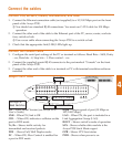
BUPS connector
AC connector
DC terminal
block