Cyclades-PR1000
Chapter 14 - Virtual Private Network Configuration 107
STEP THREE
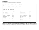
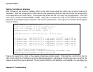
Use the menu item INFO =>SHOW ROUTING TABLE to confirm that the other Remote Security Gateways (RSGs),
and all the networks included in the Remote Security Networks, are reachable. In the example, this would require
that all of the following appear in RSG3’s routing table:
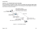
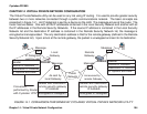
• RSG1 router IP address: 9.9.9.1
• Network connected to RSG1 that will be included in Remote Security Network 1: 10.255.255.0
• RSG2 router IP address: 20.20.20.1
• Network connected to RSG2 that will be included in Remote Security Network 2: 192.168.0.0
These IP addresses should appear as a destination or be contained in one of the destination networks listed in the
routing table. If an address is not in the routing table, add it following the instructions given in chapter 9 for static
routes.
STEP FOUR
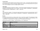
The next step is to define the devices contained in the Local Security Network. Navigate to the menu CONFIG
=>SECURITY =>VPN =>LOCAL IP NETWORKS =>ADD NETWORK. Enter the Network IP address and mask
for all devices to be included in the local network for VPN purposes. In the example, the networks 10.0.0.0 and
172.16.0.0 must be added.
Traffic from other networks attached to the router will still be routed. The only difference is that the
messages will be forwarded without processing and encryption by the VPN software.
STEP FIVE
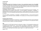
The Gateways (represented by RSG1 and RSG2 in the example) must be defined. The Router IP address for each
gateway is requested, along with a secret. This secret is not global, but rather applies to each pair of RSGs. If RSG3
defines the secret for RSG1 as rumpelstiltskin, then RSG1’s secret for RSG3 must also be rumpelstiltskin. It is critical
that the Router IP Address (as described in step two) be used, and not the IP address of the link connected to the IP
network (unless the two IP addresses happen to be the same).


