


Page 8 AXIS Q7900 Installation Guide
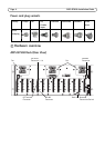
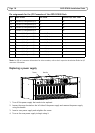
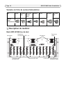
Unit connectors
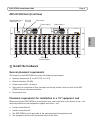
Rear connectors
Network Connector - Axis video encoder blades are designed for 10/100/1000 Mbps networks and
connect via the standard RJ-45 connector.
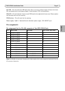
Network Connector Switch - The Network Connector Switch controls which blades are connected
to a particular network connector. The following table shows how the blades are connected based
on how the switches are set. These settings are only made during power up.
Rack ID - Sets a rack ID for all blades in the rack. Possible ID 0 to 15. The Blade ID, will correspond
to the slot number.
RS-485 Connector - Usually used for connecting Pan Tilt Zoom devices. See page 9 below for pin
assignment information.
I/O Power Connector(s) - 12VDC 100mA out. This connector could be used to supply power to
external units connected to the I/O port.
I/O Terminal Connector(s) - Provides the physical interface for up to 12 I/Os. See page 10 below
for pin assignment information.
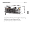
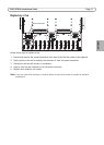
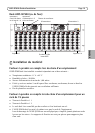
Front connectors
Network Activity LEDs 1-4 - 10/100 yellow flashes with activity, 1000M green, flashes with
activity.
Network Loop Warning 1-4 - This indicate a warning that more network packets loop around two
network cables connected to the same net when network connection switch is set in the on
position. Please reset the switches or disconnect one of the network cables.
PS1 LED - This will indicate a RED light when there is an error in Power supply 1. Please shut down
PS1 and replace with a new power supply. It also indicates if PS1 is disconnected
NET 1-2
switch
NET 2-3
switch
NET 3-4
switch
NET1
connector
NET2
connector
NET3
connector
NET4 connector
Off Off Off Blade 1-4 Blade 5-7 Blade 8-10 Blade 11-14
On Off Off Blade 1-7 Do not connect Blade 8-10 Blade 11-14
Off On Off Blade 1-4 Blade 5-10 Do not connect Blade 11-14
On On Off Blade 1-10 Do not connect Do not connect Blade 11-14
Off Off On Blade 1-4 Blade 5-7 Blade 8-14 Do not connect
On Off On Blade 1-7 Do not connect Blade 8-14 Do not connect
Off On On Blade 1-4 Blade 5-14 Do not connect Do not connect
On On On Blade 1-14 Do not connect Do not connect Do not connect