


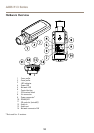

AXIS P13 Series
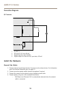
Connection Diagrams
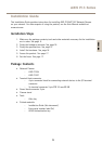
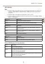
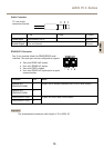
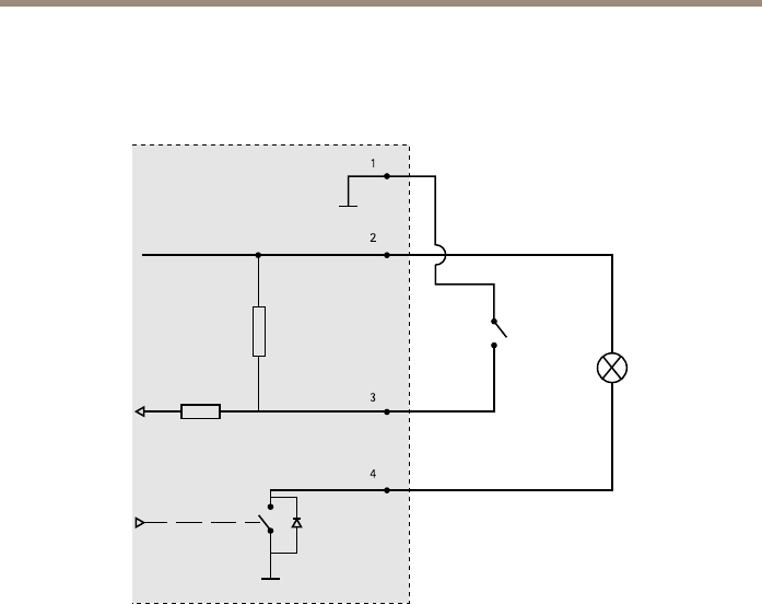
I/O Connector
1
2
3
4
1
0 V DC (-)
2
DC output 3.3 V, max 50 mA
3
Digital input 0 to max 40 V DC
4
Digital output 0 to max 40 V DC, open drain, 100 mA
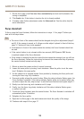
Install the Hardware
Connect the Cables
1. Connect external input/output devices if required, such as alarm devices. For information
about the terminal connector pins, see page 14 .
2. Connect an active speaker and/or external microphone if required.
3. Connect the camera to the network using a shielded network cable.
4. Connect power, using one of the methods listed below:
- PoE (Power over Ethernet). PoE is automatically detected when the network
cable is connected.
16