


2 of 18
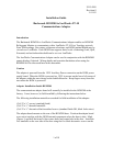
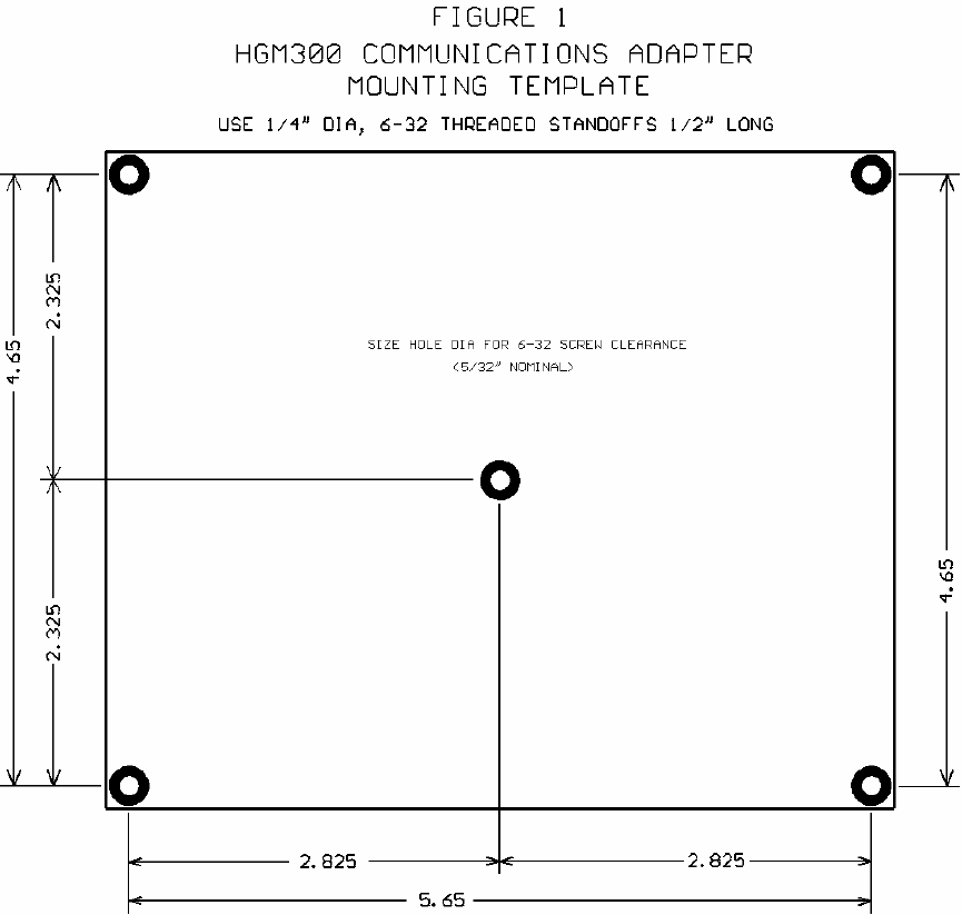
front side of the door. Position the adapter board over the standoffs mounted on the
HGM door. Install the five remaining 6-32 screws through the board and into the
standoffs and tighten.
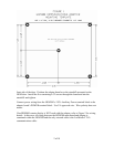
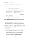
Connect power wiring from the HGM300’s 120V Auxiliary Power terminal block to the
adapter board’s POWER terminal block. Use UL approved wire. Wire polarity does not
matter.
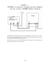
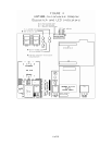
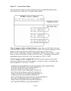
If an RDM800 remote display is NOT used with the adapter, refer to Figure 2 for wiring
details. In this case, all wiring between the HGM300 main board and adapter is
contained within the HGM300 and the only external cable is the LonWorks FT-10
communications cable.