5 of 18
Setting HGM Communication Address On Adapter
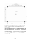
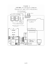
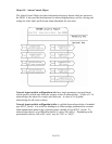
See Figure 4 for the location of adapter dipswitch ‘A’.
Switches 5-8 on the adapter’s ‘A’ dipswitch are used to match the node address set on the
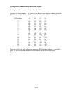
HGM’s address dipswitch (on HGM main board). Values from 0-15 are possible:
HGM address A5 A6 A7 A8
----------------- ----------------------------------------------
0 Off Off Off Off
1 Off Off Off On
2 Off Off On Off
3 Off Off On On
4 Off On Off Off
5 Off On Off On
6 Off On On Off
7 Off On On On
8 On Off Off Off
9 On Off Off On
10 On Off On Off
11 On Off On On
12 On On Off Off
13 On On Off On
14 On On On Off
15 On On On On
Since the HGM is the only node on the adapter-to-HGM interface, address 1 is normally
used. Be sure to set the same address on the adapter and the HGM main board
dipswitches.


