


3-2 Installation
1-15HP Size A and B Controls
(For
all 15H Inverter
, 18H V
ector
, and 23H Servo).
Single Expansion Board Installation
Procedure:
1.
Be sure drive operation is terminated and secured.
2.
Remove all power sources from the control.
3. W
ait at least 5 minutes for internal capacitors to discharge.
4.
Remove the four (4) Phillips head screws that secure the
control cover.
5.
Remove the control cover
.
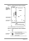
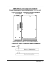
6.
Remove the #6 screw at position MH1 (upper left on the
main circuit board. See Figure 3-1.
7.
Install the long standoffs provided in the installation
hardware as shown in Figure 3-1. (Be sure the
Male/Female standof
f is at position MH1. The other three
are Female/Female.)
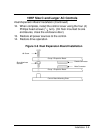
8.
Slide the expansion board male connector into the female
connector of the control board.
9.
Securely mount the expansion board to the standof
fs
installed in step 7 using #6 screws provided in the
installation hardware. See Figure 3-2.
10.
The mechanical installation of the expansion board is now
complete. Refer to Section 4 of this manual and configure
the jumpers as desired. Also complete the wiring before
you proceed to step 1
1.
11.
When complete, install the control cover using the four (4)
Phillips head screws.
12.
Restore all power sources to the control.
13.
Restore drive operation.