


Section 5
Software Setup
Software 5-1
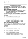
Configure Control Software
After
the Resolver to Digital Interface board has been installed
and the DIP switches are correctly set, the control software must
be configured.
Series 18H and 22H V
ector Controls
Note:
When the Resolver to Digital Interface board is installed,
the encoder inputs to the control are automatically
disabled (J1 pins 23 to 30).
The value of the Level 2, MOT
OR DA
T
A Block, “Resolver Speed”
parameter (P2509) must be set to the correct speed value.
Procedure:
1.
At the keypad, access the Level 2 Blocks.
2.
Scroll to and access the Motor Data Block.
3.
Access the Resolver Speed parameter
.
Change its’ value to the Resolver Speed T
ype.
Example: For a 2 pole Resolver
, enter 1 (1 Speed).
Example: For a 6 pole Resolver
, enter 3 (3 Speed).
Series 19H and 20H DC SCR Controls
The value of the Level 2, MOT
OR DA
T
A Block, “Feedback T
ype”
parameter (P2507) and “Resolver Speed” parameter (P2509)
must be set.
Procedure:
1.
At the keypad, access the Level 2 Blocks.
2.
Scroll to and access the Motor Data Block.
3. Access the Feedback T
ype parameter
.
Change its’ value to RESOL
VER.
4.
Access the Resolver Speed parameter
.
Change its’ value to the Resolver Speed T
ype.
Example: For a 2 pole Resolver
, enter 1 (1 Speed).
Example: For a 6 pole Resolver
, enter 3 (3 Speed).