


MatrixPRO-II 3G/HD/SD-SDI Routers Rev. 1.1
MatrixPRO-II HD/3G SDI Series –User’s Guide - Rev. 1.1
20
4 LED status indication
4.1 Start-up
The LED located at the front of the router indicates the status of the router. At start-up, the
LED will alternate between red (R) and green (G) every 500ms for about two seconds. After
the start-up sequence the LED will indicate the Alarm state of the router.
There are two LEDs located at the Ethernet bus. At start-up the boot loader is searching for
update commands on the serial port for about two seconds. During this sequence both
Ethernet LEDs will be blinking. After the start-up sequence the LEDs will indicate the
Ethernet state.
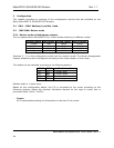
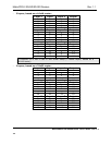
4.2 Alarm states
The LED can either be red (R), green (G), yellow (Y) or have no light (N).
The LED state is here described with twenty letters, each representing 100ms, which totals
to an alarm sequence of two seconds. The X indicates that the LED keeps the color it has the
moment the alarm sequence begins (green, yellow or no light).
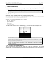
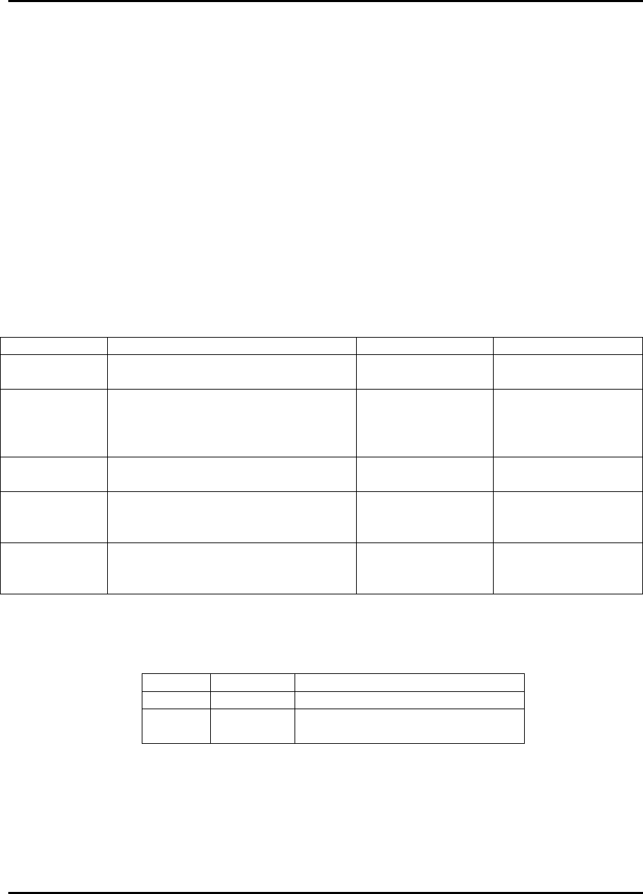
Description
LED state Alarm Comment
Continuous
green light
GGGGG GGGGG GGGGG GGGGG No alarm. Status
is OK.
Continuous
yellow light
YYYYY YYYYY YYYYY YYYYY Unable to
connect to
controller over
Ethernet.
This alarm will be
overwritten by
other alarms
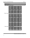
Long red
blinks
RRRRR NNNNN RRRRR NNNNN Power is too low.
One short
red blink
RXXXX XXXXX XXXXX XXXXX Power A failed Only active if
power alarm dip is
set.
Two short
red blinks
XXXXX XXXXX RXRXX XXXXX Power B failed Only active if
power alarm dip is
set.
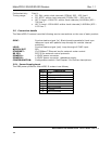
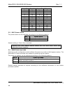
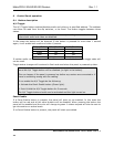
4.3 Ethernet states
The LEDs that are located at the Ethernet bus will after the Start-up sequence indicate the
Ethernet states:
On Off / Blinking
Green Valid link No link
Yellow No data Data is transmitted or
received