


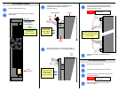
DX-700 Module Removal
Note
DX-700 Module Insertion
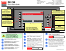
Chassis
Module
Latch
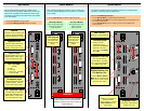
Insert module
until the latch
stops against
the chassis
Ensure that DX-700 power is off.
1
Orient the module so that the power connector is
at the bottom.
2
Power
Connector
Carefully insert the module, and push it into the
chassis until the module’s top latch stops
against the chassis.
3
Rear View:
• System Module
• Input Module
• Output Modules
The rear panels of all
three DX-700
modules are identical.
Raise the top latch until you can slide the module
farther into the chassis — up to the latch’s pivot point.
4
Pivot
Point
Raise latch, slide
module farther in,
until it stops
against pivot point
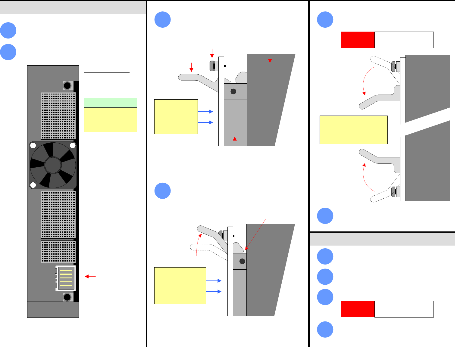
Simultaneously push both latches towards the
center of the module, until the module is fully
seated against the chassis.
5
Simultaneously push both
latches toward the center
of the module
CAUTION
Always push both latches
simultaneously.
Tighten both retaining screws to secure the
module.
6
1
Ensure that DX-700 power is off.
2
Loosen both retaining screws on the module.
3
Simultaneously push both latches away from the
center of the module.
4
When both latches are clear of the chassis,
remove the module.
Retaining Screw
CAUTION
Always push both latches
simultaneously.