Storing Spare Modules
Incorrect Justification
Blank
Input
Input
Output
System
Power
Output
Input
Input
Incorrect Justification
Blank
Blank
Input
Input
Output
System
Power
Blank
Output
Correct Justification
Correct Justification
Correct Justification
Incorrect Justification
DX-700 User’s Guide
DX-700 Module Configuration Rules
Format Connection Table
Input
Connector
Composite
Video
S-Video
(Y/C)
YUV
(YP
b
P
r
)
RGB
Sync on Green
Y / COMP
C / P
b
P
r
(Luma) (Luma) (G)
(Chroma) (P
b
) (B)
(P
r
) (R)
For complete details on all installation, setup, configuration and operations procedures, please refer to
the DX-700 User’s Guide.
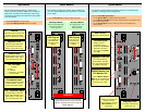
DX-700 supports a wide number of system configurations. Input and output modules are installed in
“banks,” consisting of one (or more) input modules, and either one or two output modules (with two
being the maximum allowed in a bank). By definition, a “bank” is a way of combining inputs and
outputs into independent video processors that are capable of driving one (or more) LED walls.
Please remember the following important “module” configuration rules.
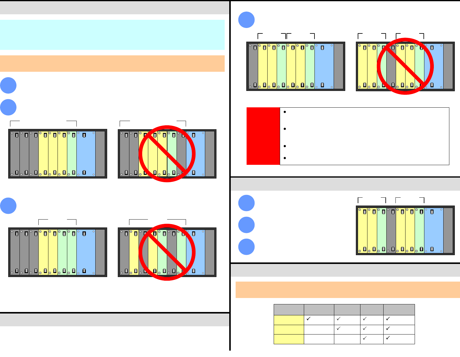
In the most basic of DX-700 “single bank” configurations, you must have at least one input
module and one output module — to route video to an LED wall.
1
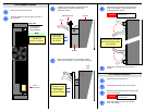
As you face the rear of the chassis, the right-most module in the Input/Output Section must
always be an Output Module. It must always be right-justified against the System Module.
2
Input / Output Section Input / Output Section
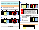
Within any bank, all modules must be adjacent to each other, with no blank panels
in-between, and all Output Module(s) are always right-justified.
3
Bank 1 Bank 1
In multi-bank configurations, all banks must be directly adjacent to one another, with no
blank panels in between.
4
Bank 2Bank 1
Blank
Blank
Blank
Input
Input
Input
Output
System
Power
Blank
Blank
Input
Input
Input
Output
System
Power
Blank
Blank
Blank
Blank
Input
Input
Output
System
Power
Output
Blank
Input
Input
Output
System
Power
Output
Input
Input
Bank 2Bank 1
IMPORTANT
With the exception of “spare” modules, if the DX-700 determines that any
modules are incorrectly installed (or missing), a Startup Diagnostic Menu
appears which prompts you to power down and re-configure your modules.
If the above prompt occurs, and provided that a System Module is properly
installed, on the Startup Diagnostic Menu you can press the DX-700
Management button, and access a subset of management functions.
The DX-700 will not recognize modules that are installed to the left of a blank
panel. They will be treated as spares.
Slots that do not contain modules must always have blank panels installed.
Configure a bank according to the rules
outlined in the “DX-700 Module
Configuration Rules” section.
1
Install a blank panel immediately to the
left of the bank’s left-most input
module.
2
In the remaining slots, insert spare
modules. These are ignored and
treated as spares.
3
Use the following table to connect various source formats to the DX-700, using the system’s
Component input (3 x BNC) on the Input Module.
Bank 1Spares
Blank
Input
Input
Output
System
Power
Output
Input
Input
P/N 26-0601004-00, Rev 02


