3-1
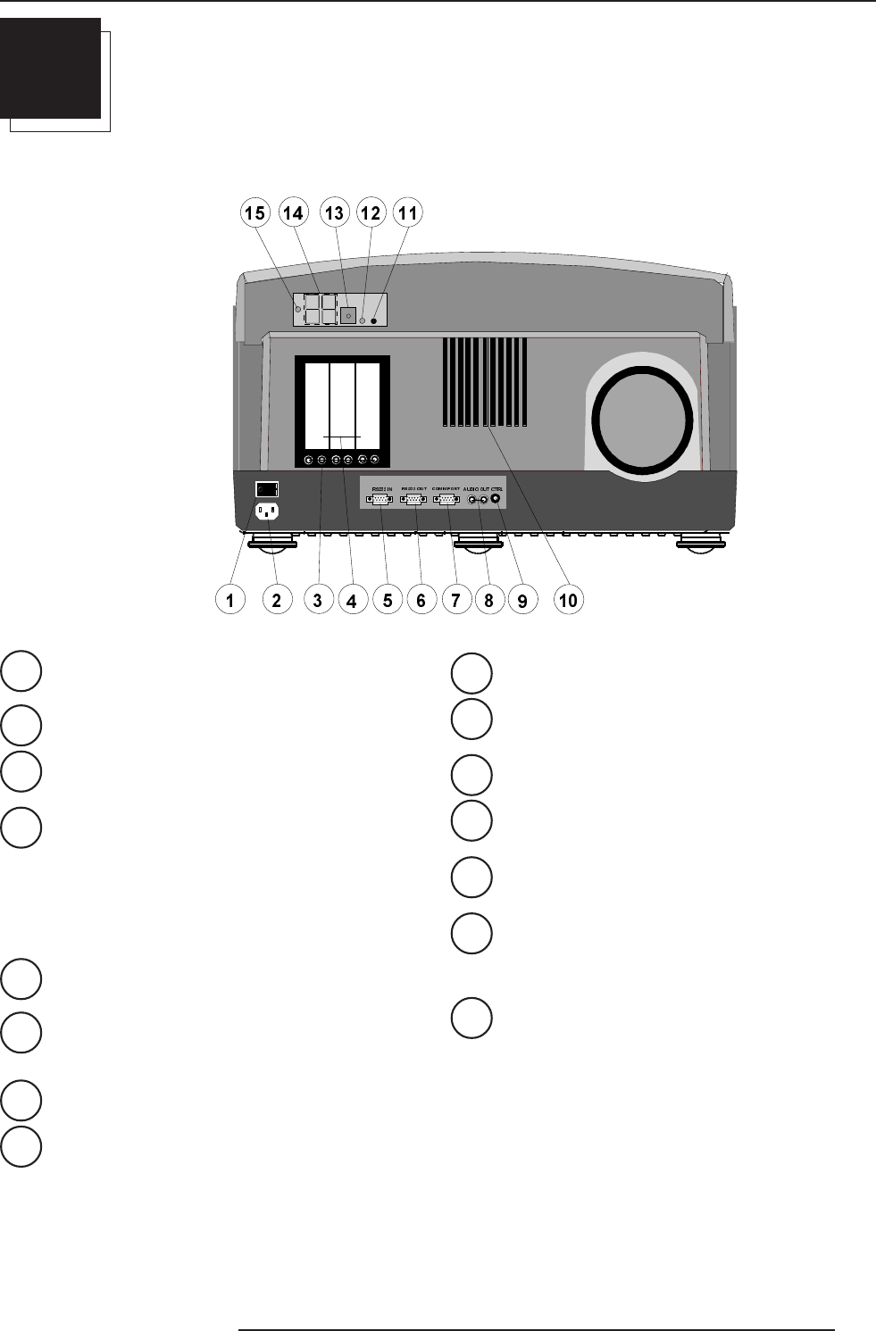
Location and Functions of Control
5975398 BARCODATA 3200 110797
3
Remote : Remote input for wired remote control.
Loudspeaker : for use in small areas only.
IR-Acknowledged : IR signals are recognized (green
led).
IR-Received : IR signals are received but not recognized
by the projector (red led).
IR receiver : Receiver for control signals transmitted from
the RCU.
Diagnostics code : a) Source number
b) Error code : A two digits error code is displayed when
something goes wrong inside the projector.
Projector mode indication : Indicates the status of the
projector.
No lighting up : Power switch is not pressed.
Red lighting up : Power switch is pressed, projector in
stand by mode.
Green lighting up : Projector in operational mode.
1
Power switch : '1' = on, '0' = off
Power input : Autoranging from 90 to 250 Vac.
Audio input for Video signals only.
Input slots : The projector has modular input facilities.
3 input modules can be inserted. The sequence of
insertion has no importance.
The following modules can be inserted :
- Video, S-Video (PAL, SECAM, NTSC) input
- RGBS/RGsB analog input
- RGB3S/RG3sB input
- Component Video input
RS232 IN : To allow communication with external com-
puter, e.g. IBM PC or compatible, Macintosh ...
RS232 OUT : Used to connect to next projector, RS232IN
plug (communication link for PC or MAC to the next
projector).
Communication port : Allows communication with the
800 peripherals.
Audio output.
3
2
4
5
6
7
8
9
10
11
12
13
14
15
LOCATION AND FUNCTION OF CONTROLS
Front panel terminology


