


Introduction to the BayStack 303 and 304 Ethernet Switches
893-01010-A 1-7
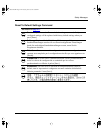
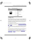
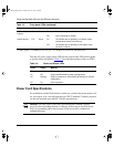
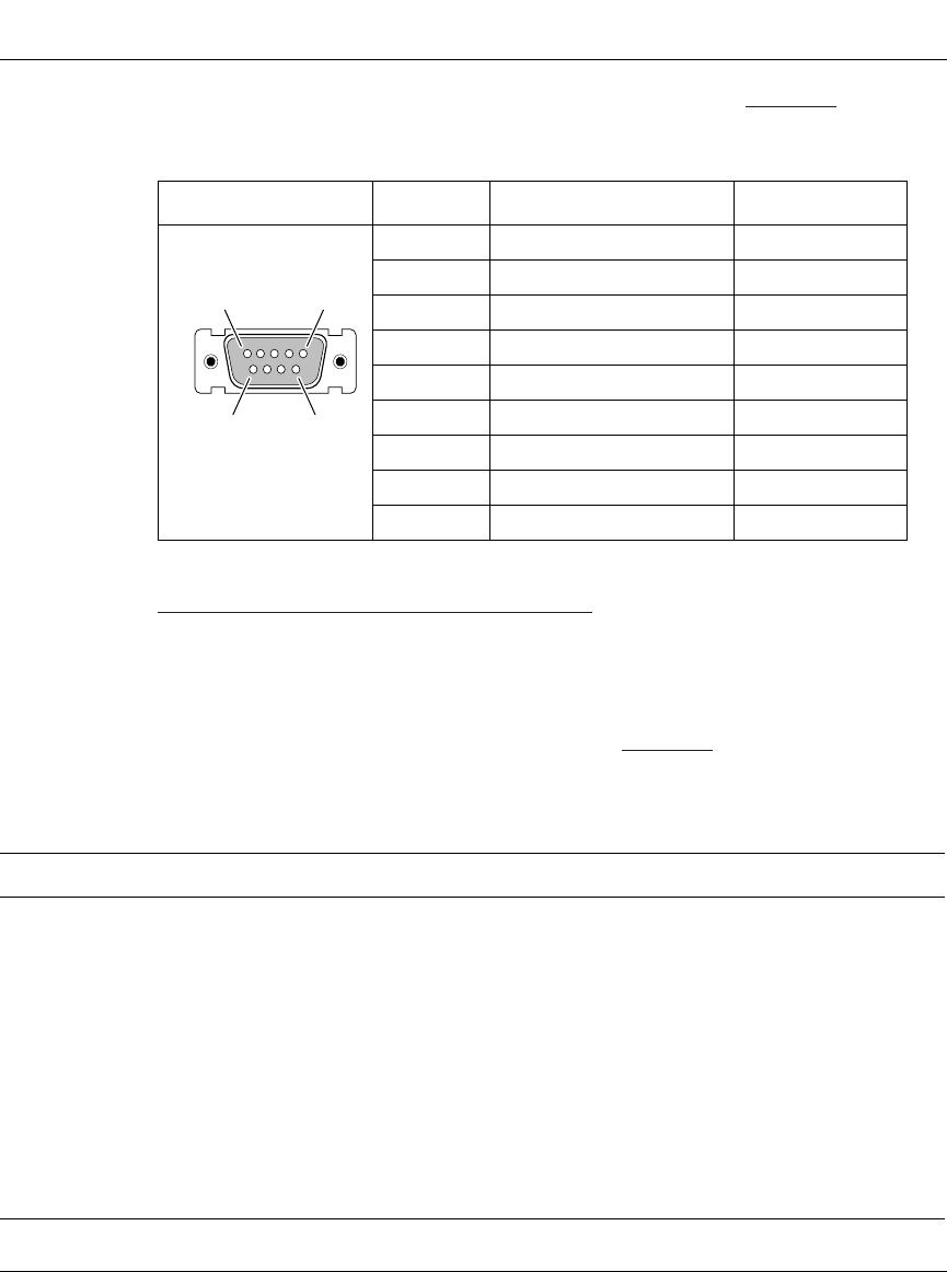
The console port connector pin assignments are described in Table 1-2.
For information about connecting a terminal to the console port, refer to
Chapter 2, “Installing the BayStack Switches.”
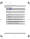
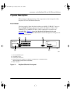
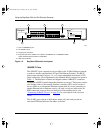
LEDs
The LEDs on the front panel of the BayStack switches help you to identify the
unit port status and MDA operational mode (see T
able 1-3). LEDs associated with
the RJ-45 port connectors allow you to identify the link status of each port.
Table 1-2. DB-9 connector pin assignments
Pins Signal name Direction
1 Not used
2 Transmit data, TD To terminal
3 Receive data, RD From terminal
4 Not used
5 Common signal ground
6 Not used
7 Not used
8 Not used
9 Not used
Table 1-3. Front-panel LEDs
Type Label Color State Meaning
Link status of
each port
Link Green On
Off
Link is active and connected correctly.
Link is inoperative or improperly connected.
Unit AC
power supply
status
Power Green On
Off
Switch is receiving valid AC power.
Switch is not receiving valid AC power, or internal power
supply has failed.
System
status
Status Green On
Blinking
Off
Unit is operating properly.
Unit is performing self-tests or network configuration.
A system fault has occurred.
1
5
6
9
DB-9
3166.3
89301010.BK Page 7 Tuesday, June 10, 1997 8:00 PM