


Documentation Number 11401198 Manual 9
B&B Electronics -- PO Box 1040 -- Ottawa, IL 61350
PH (815) 433-5100 -- FAX (815) 433-5105
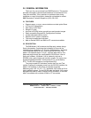
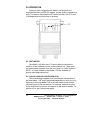
4.0 INSTALLATION
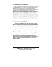
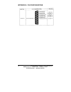
The Model 1140 is easy to install. After configuring the DIP
switches, simply connect the two fiber cables and then connect the
RS-232 interface. Figure 5 shows the location of the fiber
connections on the Model 1140's rear panel.
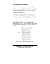
Figure 5. Close-up of ST and SMA connections
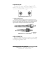
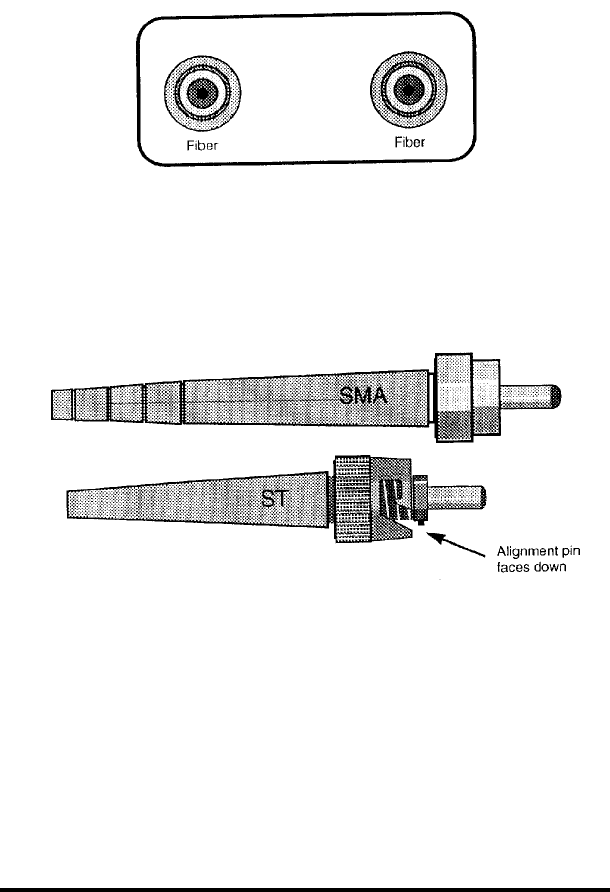
4.1 FIBER CONNECTIONS
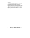
The Model 1140 short range modems are designed to work in
pairs. You will need one at each end of a dual fiber cable. This cable
connects to each Model 1140 using either an ST or SMA connector.
Figure 6 shows a close up of each of these connector types.
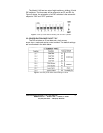
Figure 6. Close-up of ST and SMA connections
4.2 RS-232 CONNECTION
Because the Model 1140 is designed to behave as either a DCE
or a DTE device, it does not need special cables to operate. Always
use a straight-through RS-232 cable.