


4 Documentation Number 11401198 Manual
B&B Electronics -- PO Box 1040 -- Ottawa, IL 61350
PH (815) 433-5100 -- FAX (815) 433-5105
3.0 CONFIGURATION OVERVIEW
The Model 1140 is fairly simple to install and is ruggedly
designed for excellent reliability: just set it and forget it. The
following instructions will help you set up and install the Model 1140
properly. If you have any questions, don't hesitate to call B&B’s
Technical Support Department at (815) 433-5100 (8-5 PM, CST).
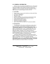
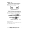
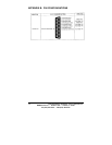
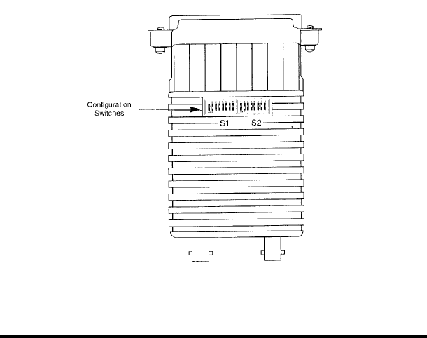
3.1 CONFIGURATION SWITCHES
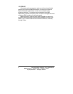
The Model 1140 uses a unique set of 16 external mini DIP
switches that allow configuration to an extremely wide range of
applications. These 16 DIP switches are grouped in two eight-switch
sets, and are externally accessible from the underside of the Model
1140 (see Figure 1). Since all configuration DIP switches are
externally accessible, there is no need to open the Model 1140's
case for configuration.
The configuration switches allow you to select data rates,
clocking methods, V.52 & V54 tests, word lengths, extended
signaling rates, async. or sync. mode. The drawings, text and tables
on the following pages describe all switch locations, positions and
functions.
Figure 1. Model 1140 Configuration Switches External Position