


1.815.433.5100
www.bb-elec.com
70
Communication
USB
Wireless
Serial
USB
Wireless Proprietary RF
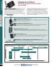
R.F. Antenna and Cable Selection
When designing an antenna system there are several items to
consider. Factors that affect the performance of the antennas
are highlighted below. An RF communications system should
be designed such that more than the absolute minimum signal
level arrives at the receiver. This will allow some “link margin”
in situations where conditions change and the environment
degrades the signal.
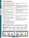
Typical radiation patterns using Yagi and Dipole type antennas.
Radio Output Power. RF power is rated in watts or milli-watts.
T
ypical B&B Electronics Zlinx products are rated in 1mw,
10mw, 100mw, 500mw and 1watt, outputs. As RF power
increases so will the current demand on the power supplying
your system.
Radio Receive Sensitivity. Receive sensitivity is basically the ability
to detect and decode a specific radio frequency. Typically this is
measured in dBm - the lower the better. Typical Zlinx products
are approximately -114dBm.
Transmit/Receive Distance. Keep in mind that if you have lots of
transmit power but poor receive sensitivity, bidirectional
communication may be a problem. The type of cable and antenna
used will affect the receive sensitivity and RF output power.
Cable Impedance. It’s important to select a cable that matches
the radio’s impedance. A mismatch will cause the radio link to
become inefficient or may cause damage to the radio.
Antenna Type. If at all possible your system’s antennas should be
a
ble to “see” each other. This is not always possible so it’s critical
to select the proper antenna components to keep signal loss or
decrease receive sensitivity. If obstacles are present, you may
consider a higher gain antenna.
Cable Type. Selecting the incorrect cable could cause
significant signal loss. A rule of thumb is for every 3db of loss,
your system will lose one half the output power emitted from
the radio. Visit our antenna selection tech paper a helpful
selection guide and more information:
www.bb-elec.com/techpapers.
Obstacles. Obstacles are always a problem. General rule: Try
to avoid them. When placing an antenna, keep in mind that
trees grow, new buildings are constructed. Plan for future
obstructions.
Cable Type Loss at 900 MHz - per 100 feet Loss at 2.4 GHz - per 100 feet Diameter
LMR-195 11.5 dB 19.0 dB 0.195 in.
LMR-400 3.9 dB 6.8 dB 0.405 in.
Frequency and Wattage 300 feet 1000 feet 1 mile 5 miles 10 miles
900 MHz, 100 mW 2.1 dB 2.1 dB >6 dB >10 dB n/a
900 MHz, 1 W 2.1 dB 2.1 dB >3 dB >6 dB >10 dB
2.4 GHz, 50 mW 2.1 dB >6 dB >10 dB n/a n/a
2.4 GHz, Zigbee 2.1 dB >6 dB >10 dB n/a n/a
Cable Specifications
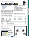
Antenna Gain Rule-of-Thumb
More is Not Better…
Keeping the above in mind, one of the most important
components in an antenna system is the transmission cable.
The wrong type, wrong impedance, wrong length, etc., and
your system could go south quick. When selecting RF coax
type cable keep cable runs as short as possible. Long cable
runs will cause additional signal loss.
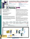
Peer to Peer vs. Peer to Multi-Peer…
When selecting an antenna also keep in mind the type of
system architecture. Simple systems, such as peer-to-peer, can
be easily designed using Yagi antennas on both ends. A multi-
peer system, such as a Modbus master to several slave devices,
needs a little more thought. When designing a multi-peer
system the master needs to communicate to all the respective
slave devices. This is typically accomplished by designing an
omni-directional antenna on the master and Yagi antennas
pointing at the master antenna.
Antenna Selection…
The same rule applies for the gain of an antenna: for every 3db
of gain, you will double the effective radiated power out of the
respective antenna. A gain of 8.1db using a 100wm radio is
approximately 270mw of output power. (Keep in mind we
have not included any cable or connector losses.)