


Documentation Number 3PCIOSD1x-3903m Manual Chapter 2 11
B&B Electronics Mfg Co – 707 Dayton Rd - PO Box 1040 - Ottawa IL 61350 - Ph 815-433-5100 - Fax 815-433-5104
B&B Electronics Ltd – Westlink Comm. Pk. – Oranmore, Galway, Ireland – Ph +353 91-792444 – Fax +353 91-792445
The receiver can also be enabled and disabled, a useful feature in
two-wire communications to prevent the transmitted data from
"echoing back" on its own receiver. The second jumper "RX" of JP4
determines the receiver mode. When the jumpers are placed in the
“485” position, the "echo" is turned off. This is achieved by disabling
the receiver when the transmit driver is enabled. Placing this jumper
in the “422” position will hold the receiver enabled at all times. More
information on RS-422 communications can be found in B&B’s free
RS-422/485 Application Note (available on our websites).
RS-422 and RS-485 Termination
A 120Ω termination resistor has been provided for the RS-422/485
receiver. Note that termination should only be used in systems with
both high baud rates (>19200) and over several thousand feet of
cable. If a value other than 120 Ω is desired, space for a through-
hole resistor has been provided on the board adjacent to the surface
mount termination resistor. This through-hole termination resistor is
labeled as RTAB while the surface mount termination resistor is
labeled as RTAA. See B&B’s free RS-422/485 Application Note,
Termination section, page 16, for more information (available on our
websites).
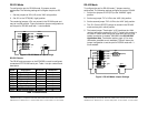
RS-485 Network Biasing
Biasing is required on an RS-485 network to hold the network in the
marking state between transmissions. The 3PCIOSD1x RS-485
receiver is biased with a 4.7 KΩ pull-up resistor (R28A) on the
Receive Data B line and a 4.7 KΩ pull-down resistor (R29A) on the
Receive Data A line. These values are usually adequate for
networks without termination and small numbers of nodes. For more
complex networks, the user must calculate the required value and
replace these resistors. Space for through-hole resistors has been
provided over the top of the surface mount components placed at
the factory. The through-hole resistor for the pull-up is marked as
R28B and the pull-down is marked as R29B.
12 Chapter 2 Documentation Number 3PCIOSD1x-3903m Manual
B&B Electronics Mfg Co – 707 Dayton Rd - PO Box 1040 - Ottawa IL 61350 - Ph 815-433-5100 - Fax 815-433-5104
B&B Electronics Ltd – Westlink Comm. Pk. – Oranmore, Galway, Ireland – Ph +353 91-792444 – Fax +353 91-792445
4 X Baud Rate Option
Baud rates higher than 115,200 are possible with the 3PCIOSD1x
card in RS-232, 422, or 485 mode. Jumper JP3 controls the clock
frequency supplied to the UART. By moving this jumper to the “*4”
(left) position, the clock frequency is increased from 1.8432 to
7.3728 MHz. This multiplies all UART baud rates by 4 times. For
example, if the software is set for 57.6K baud, the actual baud rate
will be increased by a factor of four to 230.4K baud. In many
systems, these higher baud rates can improve throughput
significantly. However, remember that baud rates and actual
throughput are only proportional if the system can keep up with the
communications, otherwise increasing the baud rate effectively only
increases the idle time between characters.
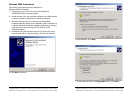
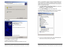
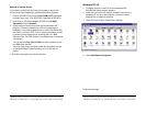
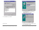
Installing the Card
1. Ground yourself by touching the metal chassis of the computer
to discharge any static electricity.
2. Turn the power to your computer off and unplug the power cord.
3. Remove the cover of the computer.
4. Locate a free PCI expansion slot.
5. Remove the expansion slot cover. Save the screw for
installation of the 3PCIOSD1x card.
6. Install the card into the unused slot. Be certain that the card is
inserted completely (fully seated) in the slot.
7. Secure the card with the mounting screw from step 5.
8. Replace the cover, plug in the power cord, and power up the
system.