


Manual Documentation Number: UEC100M/4-2305 5
B&B Electronics Mfg Co Inc – 707 Dayton Rd - PO Box 1040 - Ottawa IL 61350 - Ph 815-433-5100 - Fax 815-433-5104 – www.bb-elec.com
B&B Electronics – Westlink Commercial Park – Oranmore, Galway, Ireland – Ph +353 91-792444 – Fax +353 91-792445 – www.bb-europe.com
Before You Begin
Before you can install the Ulinx Extender, you need to prepare your site.
1. Determine where the host computer is to be located and set up the
computer.
2. Determine where you want to locate the USB device(s).
3. Decide whether the power adapter is to be connected to the Local
Unit or the Remote Unit (see the discussion of power handling on
page 4).
4. If you are using surface cabling, ensure you have enough Category
5 UTP cabling to connect the two locations.
OR
If you are using premise cabling, ensure Category 5 UTP cabling
is installed between the two locations, with Category 5
information outlets located near both the computer and the USB
device.
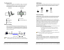
Installing the Local Unit
1. Place the Local Unit near the host computer.
2. If the power adapter is to be located with the Local Unit:
a) Plug the power adapter into a suitable AC outlet.
b) Connect the power adapter to the Local Unit.
3. Plug the Type B connector on the USB cable (included) into the
Host port on the Local Unit.
4. Plug the Type A connector on the USB cable into the USB port on
the computer.
Installing the Remote Unit
1. Place the Remote Unit near the USB device(s).
2. If the power adapter is to be located with the Remote Unit:
a) Plug the power adapter into a suitable AC outlet.
b) Connect the power adapter to the Remote Unit.
6
Manual Documentation Number: UEC100M/4-2305
B&B Electronics Mfg Co Inc – 707 Dayton Rd - PO Box 1040 - Ottawa IL 61350 - Ph 815-433-5100 - Fax 815-433-5104 – www.bb-elec.com
B&B Electronics – Westlink Commercial Park – Oranmore, Galway, Ireland – Ph +353 91-792444 – Fax +353 91-792445 – www.bb-europe.com
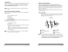
Connecting the Local Unit to the Remote Unit
NOTE:
To ensure proper operation, we recommend that only Category 5
or better, Unshielded Twisted Pair (UTP) cabling be used to
connect the Local Unit to the Remote Unit. The UTP cabling must
have a straight-through conductor configuration with no
crossovers, and must be terminated with 8-conductor RJ45
connectors at both ends.
With Surface Cabling
1. Plug one end of the Category 5 UTP cabling (not included) into the
Link port on the Local Unit.
2. Plug the other end of the Category 5 UTP cabling into the Link port
on the Remote Unit.
With Premise Cabling
1. Plug one end of a Category 5 patch cord (not included) into the Link
port on the Local Unit.
2. Plug the other end of the patch cord into the Category 5 information
outlet near the host computer.
3. Plug one end of the second Category 5 patch cord (not included)
into the Link port on the Remote Unit.
4. Plug the other end of the second patch cord into the Category 5
information outlet near the USB device.
NOTE: The maximum length of the Category 5 UTP cable, including
patch cords, must not exceed 100 meters.
Checking the Installation
1. Check that the Power LEDs on the Local Unit and Remote Unit
are both on.
2. Check that the Link LEDs on the Local Unit and Remote Unit are
both on.
3. Check that the Host LED on the Local Unit is on.
4. On the host PC, open the Device Manager applet. Expand the
entry for Universal Serial Bus controllers by clicking the + sign. If
the Ulinx Extender has been installed correctly you should find it
listed as a Generic USB Hub.