


Vlinx ESR90xW Hardware
Documentation Number: ESR90xW-4905m Chapter 2 11
B&B Electronics Mfg Co Inc – 707 Dayton Rd - PO Box 1040 - Ottawa IL 61350 - Ph 815-433-5100 - Fax 815-433-5104 – www.bb-elec.com
B&B Electronics Ltd – Westlink Commercial Park – Oranmore, Galway, Ireland – Ph +353 91-792444 – Fax +353 91-792445 – www.bb-europe.com
Connectors
Configuration Port Connector
One standard RJ-45 receptacle that allows the serial server to be connected to
personal computer for programming, troubleshooting and device
configuration. A standard straight-through RJ-45 (male) Ethernet cable can
be used for this purpose. (This port is not intended to connect directly to an
Ethernet network.)
Antenna Connector
The antenna connector is a reverse SMA connector.
(An omni-directional antenna is supplied with ESR90xW wireless serial
servers. All ESR90xW serial servers are FCC-certified when the supplied
antenna is used.)
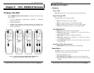
Serial Port Connector(s)
• ESR901W232: One DB-9M connector
• ESR901W485: One five-terminal removable terminal block
• ESR902W: Two DB-9M connectors
o Port 1: RS-232
o Port 2: software selectable for RS-232, RS-422 or RS-485
• ESR904W: Four DB-9M connectors
o Ports 1 & 3: RS-232
o Ports 2 & 4: software selectable for RS-232, RS-422 or RS-
485
Power Connector
The power connector is a removable terminal block with four terminals.
From top to bottom the terminals are:
Terminal
Number
Terminal
Name
Connect to Description
1
AC In
One side of AC power supply (if AC
power used)
2
AC In
Other side of AC power supply (if
AC power used)
24 VAC
1
DC GND
Negative side of DC power supply
(if DC power used)
Internally, the chassis ground of the
Server is connected to this terminal.
2 DC power
supply
Positive side of DC power supply (if
DC power used)
+12VDC to 30 VDC
Vlinx ESR90xW Hardware
12 Chapter 2 Documentation Number: ESR90xW-4905m
B&B Electronics Mfg Co Inc – 707 Dayton Rd - PO Box 1040 - Ottawa IL 61350 - Ph 815-433-5100 - Fax 815-433-5104 – www.bb-elec.com
B&B Electronics Ltd – Westlink Commercial Park – Oranmore, Galway, Ireland – Ph +353 91-792444 – Fax +353 91-792445 – www.bb-europe.com
RS-485 Receiver Biasing
Vlinx ESR90xW wireless serial servers provide built-in receiver biasing on
RS-485 ports (includes the 902W485 port, 902W Port 2 and 904W Ports 2
and 4). The Data(+) line is pulled up to 3.3V supply using a 4.7 kΩ resistor
and the Data(-) line is pulled down to ground, also using a 4.7 kΩ resistor.
RS-422/485 Terminating
If a terminating resistor is deemed necessary, for RS-422 operation typically
a 120 Ω resistor would be connected across the Receive Data(+) and Receive
Data(-) lines. For RS-485 operation the resistor would be connected across
the Data(+) and Data(-) lines.
For more information on Receiver Biasing and RS-422/485 Terminating access the
B&B Electronics RS-422/485 Application Note available at www.bb-elec.com)
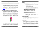
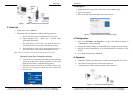
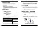
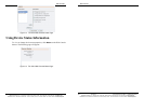
Connections for Server Configuration
Vlinx ESR90xW Wireless Serial Servers can be configured via:
• A wired connection to a RJ-45 Ethernet connector on the ESR90xW
front panel.
• The wireless network
The wired connection is recommended for configuration, especially when
configuring wireless settings, to ensure communication is not lost while
changing settings.
Figure 6. Wired Connection for Configuration