


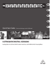

10 11ULTRAGAIN DIGITAL ADA8200 Quick Start Guide
ULTRAGAIN DIGITAL ADA8200 Controls
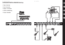
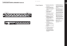
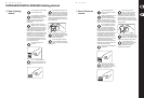
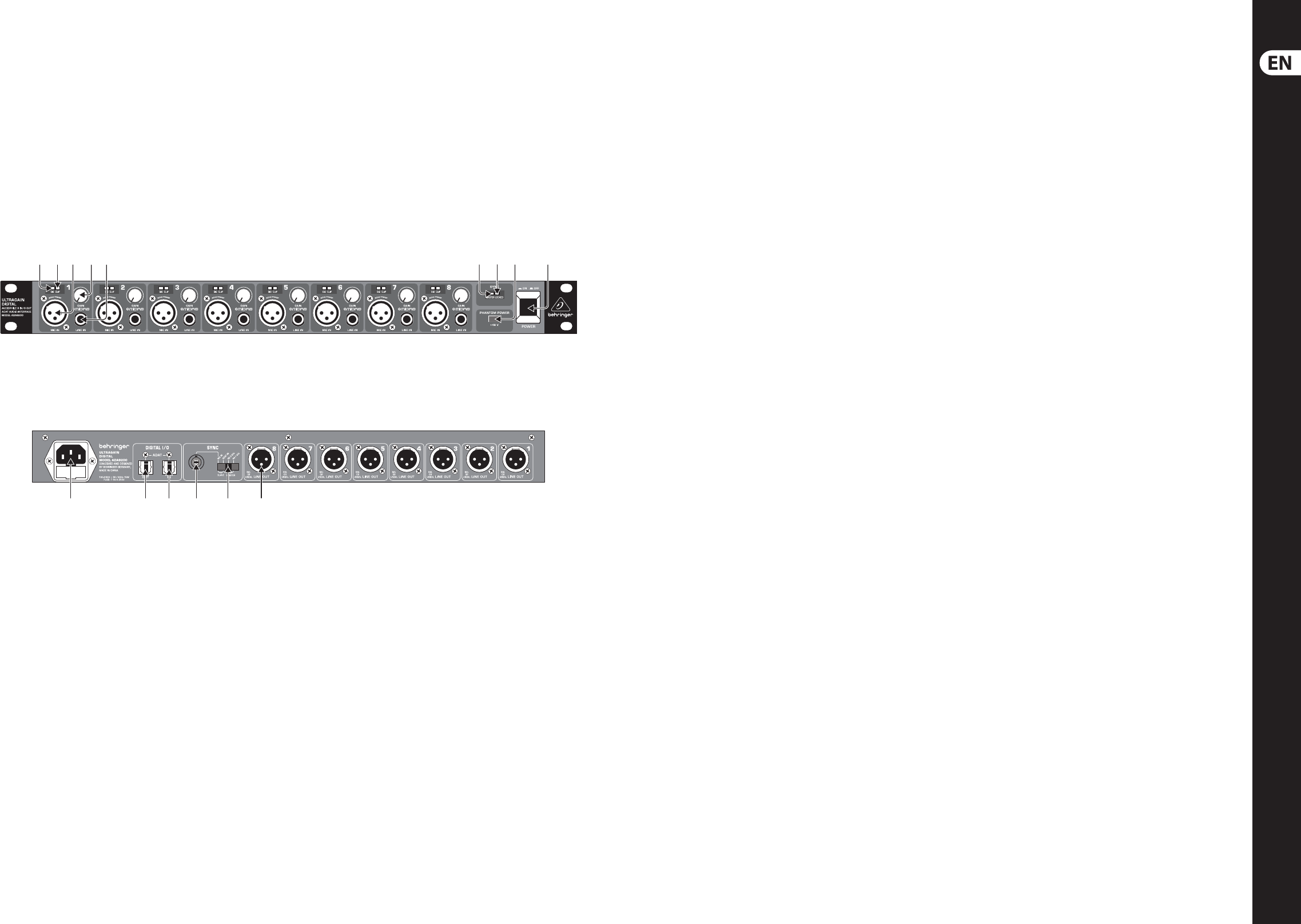
(EN) Step 2: Controls
(1) (2) (3)
(10) (12) (13) (14)(11)
(4)
(15)
(5) (6) (7) (8) (9)
(1) SIG LED indicates an input signal. This LED
illuminates when an audio signal is present
at one of the inputs.
(2) CLIP LED indicates the input signal level
is too high. This LED illuminates when the
audio signal peaks in the channel. Adjustthe
gain knob to reduce the signal level and
avoid clipping.
(3) MIC IN connects XLR microphone
or instrument input to Midas
designedpreampliers.
(4) GAIN knob adjusts the channel input level.
The gain knob adjusts the input level for
either the MIC IN or LINE IN connection.
(5) LINE IN connects ¼" TRS input at line level.
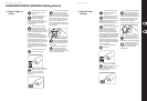
(6) SYNC MASTER LED indicates that the
ADA8200 is the master word clock source.
External word clock devices receive their
sync signal from the ADA8200.
(7) SYNC LOCKED LED illuminates when the
ADA8200 is the master word clock source,
or when receiving a valid sync signal from an
external word clock source (via either ADAT
or word clock in).
(8) PHANTOM POWER +48 V switches
the +48 V phantom power on and o.
Phantompower is active on all MIC IN inputs
when engaged.
(9) ON/OFF POWER switch turns the ADA8200
on and o.
(10) Power is supplied via an IEC cable connected
to the mains. An IEC cable is provided.
(11) 8-CHANNEL DIGITAL I/O ADAT OUT
sends 8 channels of digital audio output
from the analog inputs to an ADAT device.
Thisoutput connects to other ADAT devices
via TOSLINKcable.
(12) 8-CHANNEL DIGITAL I/O ADAT IN sends
8 channels of digital audio input from an
ADAT device to the 8 analog line outputs.
This input connects to other ADAT devices via
TOSLINK cable.
(13) Word Clock Input connects to external
devices for word clock synchronization.
This BNC connector is only active when
the SYNC selector (see 14) is switched to
SLAVE > WC IN. All devices within the
system (i.e.digital mixer, digital recorder,
or computer recording interface) must be
synchronized via a shared word clock signal.
(14) SYNC (Word clock settings selector)
designates internal or external word clock
conguration and sample rate. If the
ADA8200 is slaved to an external word
clock source, select either WC IN or ADAT IN
according to your word clock connection.
Ifthe ADA8200 is functioning as the
master word clock source for external ADAT
devices, select the appropriate sample rate
(either44.1 or 48 kHz).
(15) LINE OUT XLR male connectors send
D/A converted audio output from
ADAT IN connector.