


12
B-CONTROL FADER BCF2000/B-CONTROL ROTARY BCR2000
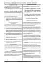
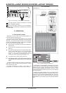
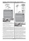
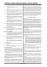
Stand Alone-Mode S-3:
Fig. 4.8: Routing and use in stand-alone mode 3
In this mode, MIDI data from the BCF2000/BCR2000 is mixed
with the data coming in at the MIDI input (merge function), but is
exported exclusively on output A. Only control data of the
B-CONTROL is available at output B.
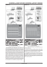
This way, you can control two MIDI devices from your
B-CONTROL, but only the device connected at OUT A can
additionally be played from the MIDI keyboard.
If you want to daisy-chain two B-CONTROLs to jointly control
several MIDI devices, you need to connect OUT A of the first
B-CONTROL to MIDI IN of the second B-CONTROL. OUT A of
the second B-CONTROL needs to be connected to the MIDI input
of the effects unit. If additional MIDI devices need to be talked
to, please connect the THRU port of one MIDI device to the IN
port of the next MIDI device. This way, with different MIDI channel
assignments, each MIDI device can be controlled from each one
of the B-CONTROLs.
If additional MIDI inputs are needed, then external MIDI merge boxes
must be used. For example, if your sound module only has one MIDI
IN connector, and you want to control if from several MIDI controllers
and from a keyboard, you will need a 2-in/1-out merge box.
If additional MIDI outputs are required, you will need external thru
boxes. With more complex MIDI setups, thru boxes are preferred
to using longer thru chains to prevent data transmission problems.
If you dont require the response function during software control,
you can connect as many BCF2000/BCR2000s as you want per
MIDI. The last B-CONTROL in the chain is then connected to the
MIDI IN input of your computer. This way, you can control nearly
as many channels of a software mixer as you wish. However,
keep in mind that all devices must share 16 MIDI channels.
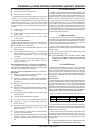
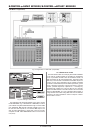
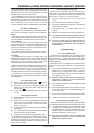
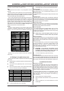
Stand Alone Mode S-4:
Fig. 4.9: Routing and use in stand-alone mode 4
The Stand Alone mode S-4 is very similar to mode S-2, with
the difference that the merge function is not available. This mode
is ideally suited for connecting to the MIDI interface of a computer
without a USB connector. The B-CONTROL routes the incoming
data to the MIDI output B (THE THRU function). MIDI control
commands are laid out at output A. This way, parameter feedback
is possible without the danger of creating a MIDI loop.
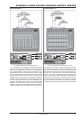
Connect the MIDI output on the MIDI interface of your computer
to the MIDI IN input on the B-CONTROL. Connect OUT A to the
MIDI input on the interface. An additional MIDI receiver can be
connected to OUT B. An expansion using a second B-CONTROL
is also conceivable. To do that, connect the B output with MIDI IN
on the next MIDI receiver. To send MIDI commands from several
units to your PC, use an external MIDI merge box.
Important information about stand-alone modes:
With the wiring examples shown here, the parameter values of
the controlled devices can be shown on the B-CONTROLs LEDs
(parameter feedback). If this is important to you, you will have to
connect MIDI IN to the MIDI output of the device you are
controlling. Of course, the hardware unit you are using has to
support sending back the parameter values. If in doubt, check
the user manual of the equipment you are using.
4. OPERATION