


15
B-CONTROL FADER BCF2000/B-CONTROL ROTARY BCR2000
4. OPERATION
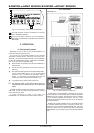
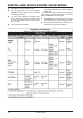
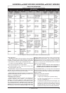
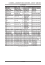
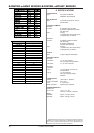
Tab. 4.2: Assignment of the push encoders in EDIT mode (CONTINUOUS types)
Table explanation:
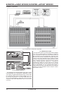
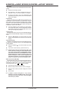
All settings in the EDIT mode are made by turning the push
encoders. Pressing the push encoder displays its current value.
In addition, the setting options depend on whether the selected
control element is a SWITCH type or CONTINUOUS type.
In the EDIT mode, Push Encoder 1 selects (by turning) the
type of command assigned to a control element.
With Push Encoder 2, select a MIDI channel through which
that control elements data is sent.
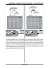
Push Encoders 3 - 5 set parameters and values for the selected
MIDI type. They vary depending on the MIDI function. More details
about this subject can be found later in this chapter.
Push Encoder 6 (Controller Mode) selects how the previously
selected control element behaves, depending on whether it is a
SWITCH or a CONTINUOUS type.
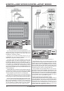
CONTINUOUS-type elements:
CONTINUOUS-type element controls are divided into
Absolute, Absolute (14 bit), Relative 1 (2nd complement),
Relative 2 (binary offset), Relative 3 (MSB, most significant
bit), Relative 1 (14 bit), Relative 2 (14 bit), Relative 3 (14 bit)
and Increment/Decrement. Absolute means absolute data
values although jumps may occur when changing values. With
Relative, the current parameter value is continued independently
from the position of the control. Absolute (14-Bit) or one of the
Relative (14-Bit) modes are standard modes for value changes
at NRPNs with high resolution. This is necessary with some
software mixers if more than 128 steps are needed. Increment/
Decrement serves as a step-by-step increase or decrease of
values by using the Data Increment/Decrement commands
(see list 5.1 in the appendix).
+ The classic controler mode for most applications is
absolute. All other modes have to be supported by
the MIDI software or the device to be controlled.
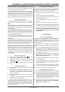
Using Push Encoder 7, you can adjust how control elements
display information. Depending on whether you are dealing with
an encoder, push encoder, fader or foot pedal, there are different
options available:
LED display of the push encoders:
OFF The LED circle remains off.
1d (1 digit): Only one LED lights up (standard setting).
1d- The LED circle operates similar to 1d, but when the
value is 0, no LED lights up.
2d The display of the LED circles occurs in two stages. If you
slowly turn the encoder from left to right, at first only one
LED lights up, and then the next LED lights up while the
previous LED goes out, and so on. This way, even the
slightest value changes can be accurately represented.