


27
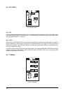
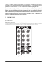
A-channel line inputs
These accept balanced or unbalanced 1/4" jacks, tip = hot, ring = cold and sleeve = ground/screen.
Mic inputs
These are via XLR-type connectors, wired pin 1 = ground, pin 2 = hot and pin 3 = cold, for balanced low-level
operation. Since most quality capacitor microphones require a 48 V DC offset to charge the plates, phantom
power is provided. This can be switched on or off in three blocks of eight via a switch situated below channels
8, 16 and 24.
+ Care should be taken not to plug microphones into the console (or stagebox / wallbox) while
the phantom power is on. Also, mute the monitor / PA speaker when turning phantom power
on or off. Allow one minute after powering up for the system to equilibrate before setting input
gains.
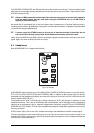
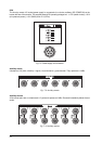
Channel inserts
These porvide for unbalanced send and return from a single stereo jack socket. Wiring is: tip = out, ring = in
and sleeve = ground/screen.
Direct outputs
This tap comes from just after the channel fader. Unbalanced 1/4" jacks.
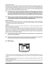
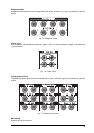
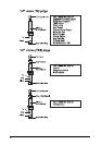
B-channel inputs/tape returns
These also accept balanced or unbalanced 1/4" jacks and are switchable, in groups of eight, between
-10 dBV (unbalanced) and +4 dBu (balanced), corresponding to the standard semi-professional and
professional operating levels and configurations respectively. Consult your multitrack manual to find out
which one applies.
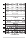
Fig. 7.10: MIX-B operating level switch and phantom power switch
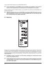
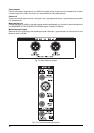
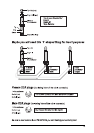
Subgroup outputs/tape sends
The eight subgroups are each connected to two stereo jack sockets, for easy patching into 16 track recording
systems (or 24 track, if you use Y-adaptors). Once again, the operating level is switchable between +4 dBu
and -10 dBV in two banks of (2x) 4.
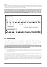
Fig. 7.11: Subgroup outputs/tape sends and operating level switch
7.2 Plug soldering guide
You will need a lot of cables for a lot of purposes. Here’s how they should look: