


26
Installation
Getting Started:
Step 1
Make sure that all servers and SMB CAT5 KVM Switches are powered
off and that each SMB CAT5 KVM Switch has been assigned a unique
BANK address.
Step 2
Place all primary and secondary KVM switches in the desired location.
Step 3
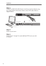
Connect the console monitor, keyboard, and mouse to the console ports of
the primary switch (BANK 00). Refer to “Connecting the Console to the SMB
CAT5 KVM Switch” on page 15.
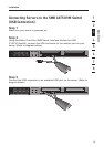
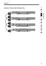
Connecting the Primary and Secondary KVM Switches:
Step 1
Using the Daisy-Chain Cable (F1D108-CBL), connect one end to the
“Primary Input/Secondary Output” port on the primary KVM switch
(BANK 00).
Step 2
Connect the other end of the Daisy-Chain Cable (F1D108-CBL) to the
“Primary Input/Secondary Output” port of the first secondary KVM switch
(BANK 01).
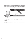
Step 3
To add additional secondary units, connect one end of the Daisy-Chain
Cable (F1D108-CBL) to the “Secondary Input” on the first secondary KVM
switch and the other end to the “Primary Input/Secondary Output” port of
the next secondary KVM switch (for example, BANK 01).
Step 4
Repeat Step 3 for additional SMB CAT5 KVM Switches you wish to
daisy-chain together.
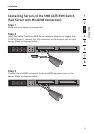
NOTE: When daisy-chaining SMB CAT5 and PRO2 KVM Switches together, be
sure to set the PRO2 KVM Switches as secondary switches only.