


14
OPERATING INSTRUCTIONS
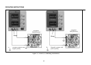
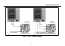
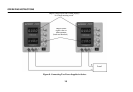
Figure 4. Typical Constant Voltag
e Operation.
c
.
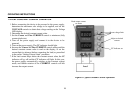
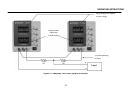
If an earth ground reference is not required, the
configuration of Fig. 3C may be used. The scheme in Fig.
3C should also be used where it is not known whether the
chassis is common with either the positive or negative
polarity.
d. If the chassis or common of the equipment being powered is
separate from both the positive and negative polarity power
inputs, use the connection shown in Fig. 3D.
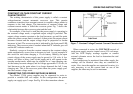
6. Observe proper polarity. If the circuit being powered is not
equipped with reverse polarity protection, damage to the circuit
can result from reverse polarity. Use color coded hook-up leads,
for convenience in identifying polarity, red for (+) and black for
(-).
7. Make sure that the hook-up leads offer sufficient current
capability and low resistance between the power supply and the
circuits being powered.
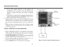
TYPICAL CONSTANT VOLTAGE OPERATION
1. Before connecting the device to be powered to the power
supply, determine the maximum safe load current for the device
to be powered and set the current limit value (see “Setting
Current Limit” procedure in this section).
2. Set Fine VOLTAGE control to center and Coarse VOLTAGE
control to minimum (fully counterclockwise).
3. Turn off power supply and connect it to the device to be
powered (see “Hook-Up” procedure in this section).
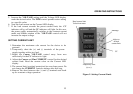
4. Turn on POWER switch. The CV indicator should light.
Read output voltage and
Current meters
Adjust to
Desired voltage
CV Indicator on
Present current
limiting
Load