


9
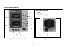
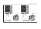
CONTROLS AND INDICATORS
INDICATORS
Either the “CC” or “CV” and the LED indicators will be lit
whenever the unit is operating, thus serving as a pilot light. The unit
automatically changes from CV to CC operation when the preset
current limit is reached.
1. C.C. (Constant Current) Indicator. Red LED lights in constant
current mode. Unit regulates output current at value set by CUR-
RENT controls.
2. C.V. (Constant Voltage ) Indicator. Green LED lights in
constant voltage mode. Unit regulates output voltage at value set
by VOLTAGE controls.
3. GREEN LED Display. 4 digit display continuously monitors
voltage.
4. RED LED Display. 4 digit display continuously monitors
current.
VOLTAGE CONTROLS
5. Coarse Control. Coarse adjustment of output voltage. Read value
on GREEN LED display.
6. Fine Control. Fine adjustment of output voltage. Read value on
GREEN LED display.
CURRENT CONTROL
7. Coarse CURRENT Control. Adjusts current limit in
constant voltage mode. Adjusts constant current value in
constant current mode. Current can be read from RED
LED display.
8. Fine Control. Adjusts current limit in constant voltage
mode. Adjusts constant current value in constant current
mode. Current can be read from RED LED display.
POWER CONTROLS
9. ON-OFF Switch.
OUTPUT TERMINALS
10. “+” Terminal (Red). Positive polarity output terminal.
11. GND Terminal. Earth and chassis ground.
12. “-” Terminal (Black). Negative polarity output
terminal.