


21
__________________________________________________________________________OPERATING INSTRUCTIONS
In the series tracking mode, the maximum output voltage of
both the “A” and “B” supplies can be simultaneously varied
with one control. The maximum “B” supply voltage can be
set to the same value of the “A” supply by using the “A”
VOLTAGE control.
The output voltage (across the two supplies) is actually
double the Volt meter reading. The actual output current
would be the value read from the mA meter (since the two
supplies are wired in series, current flowing through each
supply must be equal).
1. Set the power supplies to the TRACKING SERIES mode by
setting the TRACKING/INDEPENDENT switch to the
SERIES (left) position.
2. Set the A/B Metering switch to the A (up) position.
3. The “B” VOLTAGE AND CURRENT controls are
disabled; turn both to their minimum positions. The
maximum current is set using the “A” CURRENT control.
Follow the instructions for “Setting Current Limit”
(INDEPENDENT USE OF “A” OR “B” SUPPLY section of
this manual) using the “A” CURRENT control.
4. Adjust the output voltage to the desired level using the “A”
VOLTAGE control (remember that the actual output voltage
is double the reading on the Volt meter).
5. Turn off the power supply and the equipment to be powered
during hook-up.
6. Connect the positive polarity of the device being powered to
the red (+) terminal of the “A” power supply.
7. Connect the negative polarity of the device being powered
to the black (-) terminal of the “B” power supply.
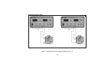
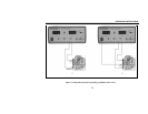
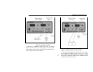
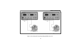
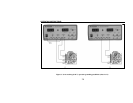
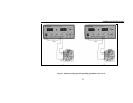
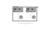
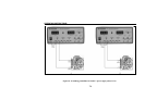
Figure 8. Series tracking (0-to-48 V) operation
grounding possibilities (sheet 3 of 3).
8. Fig. 8 illustrates the grounding possibilities when the
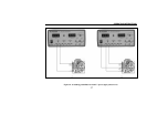
unit is used as a 0-to-48 \volt supply.
a. If the negative polarity of the equipment or circuit
being powered is also the chassis or common, it
may be grounded to earth by connecting the black
(-) terminal of the “B” supply to the green (GND)
terminal as shown in Fig. 8A.