


LE180A
4
Black Box Network Services, 724-746-550, www.blackbox.com
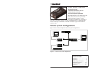
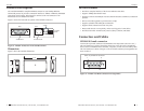
Connectors & Cables -- Continued
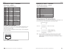
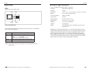
AUI connector -- continued
Pin Name Pairs Use
3 DO + Transmit Data Out +
10 DO - Pair Data Out -
11 DO S Data Out Shield
5 DI + Receive Data In +
12 DI - Pair Data In -
4 DI S Data In Shield
7 CO + Option Control Out +
15 CO - Pair Control Out -
8 CO S Control Shield
2 CI + Collision Control In +
9 CI - Pair Control In -
1 CI S Control Shield
6 VC Power Voltage Common
13 VP Pair Voltage Plus
14 VS Voltage Shield
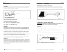
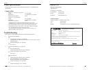
UTP cable (RJ-45 connector)
The 10Base-T, RJ-45 out jack is used to connect a 10Base-T Ethernet device via a
2-pair UTP cable. (Use category 3, 4, or 5 UTP cable.) The length of the UTP
cable can be up to 100m (328ft).
The RJ-45 connector pin configuration is shown in Figure 5. The pin assignments
are show in the Table 2..
1
2
3
45
6
7
8
Figure 5: RJ-45 Connector Pin Configuration
Table 1: AUI Male Connector Pinouts
Black Box Network Services, 724-746-550, www.blackbox.com
5
Connectors & Cables -- continued
UTP cable (RJ-45 connector) -- continued
LE180A
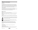
Pin Out Jack Assignments
1 Outgoing Data 1 (+)
2 Outgoing Data 2 (-)
3 Incoming Data 1 (+)
4 Not connected
5 Not connected
6 Incoming Data 2 (-)
7 Not connected
8 Not connected
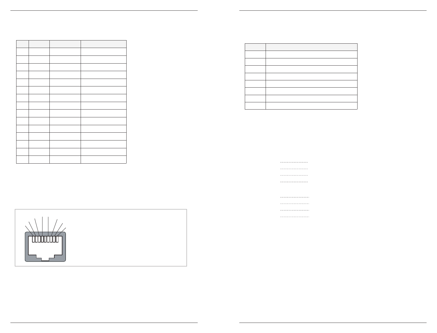
Wiring schemes for UTP cable and devices
How to install the UTP cable is determined by the characteristics of the 10Base-T UTP
port of the other device. The following shows some pinning examples:
UTP Cable Pin Wiring
1
2
3
6
1
2
3
6
10Base-T Device InputTransceiver
Pin Pin
1
2
3
6
3
6
1
2
10Base-T Output Jack
Computer 10Base-T Port
Transceiver
Transceiver
Pin Pin
Note: The device 10Base-T output jack is normally used to connect to another
10Base-T device. The vendor's 10Base-T device sometimes provides a
crossover option to set the jack as an input jack for connecting to a 10Base-T
Ethernet station.
Table 2: RJ-45 Pin Assignments