


Page 10
724-746-5500 | blackbox.com
IC401A User Manual
Chapter 2: Overview
1 2 3 4
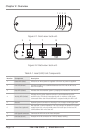
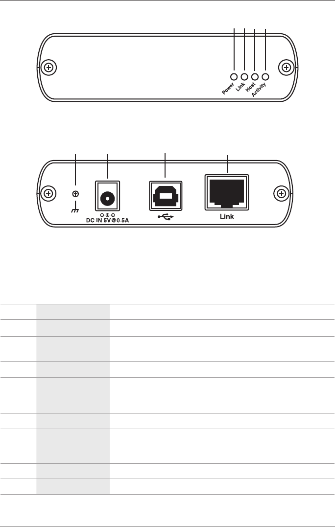
Figure 2-1. Front view: local unit.
5 6 7 8
Figure 2-2. Back view: local unit.
Table 2-1. Local (LEX) Unit Components.
Number Component Description
1 Power LED (Blue) LED turns on when power is supplied. Off when no power is supplied.
2 Link LED (Green)
Indicates a valid link is established between the LEX and the REX units
over CAT5 cabling.
3 Host LED (Green) Indicates that the extender system is properly enumerated on the host PC.
4 Activity LED (Amber)
Indicates activity when data transmission is active between the LEX
and REX units. LED blinks intermittently with or without a USB device
connected. When the LEX and REX are in suspend mode, the LED is off.
5 Ground Optional ground connection to housing of unit. Accepts an M2 type screw.
6 Power Port (optional)
Not required in normal operation. You can connect an optional 5-V power
supply to the LEX unit to provide power if the USB port on the host PC
cannot deliver 500 mA to the unit.
7 USB Type B connector Connects the LEX unit to the host computer.
8 Link Port (RJ-45) Accepts an RJ-45 connector for CAT5 (or better) cabling.