


724-746-5500 | blackbox.com
Page 10
1-Port T1/E1 Ethernet Network Extender Kit
3. Installation
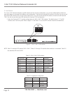
The 1-Port T1/ E1 Network Extender uses DIP switches for fast and easy configuration, so it can be installed quickly. Follow the
steps listed below to complete the installation and configuration. There are two external DIP switches on the front of the unit and
four internal DIP switches on the circuit board inside the unit. You will use the external DIP switches for both full and Fractional
T1/E1. You will only use the internal DIP switches for Fractional T1/E1 configuration.
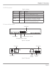
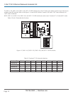
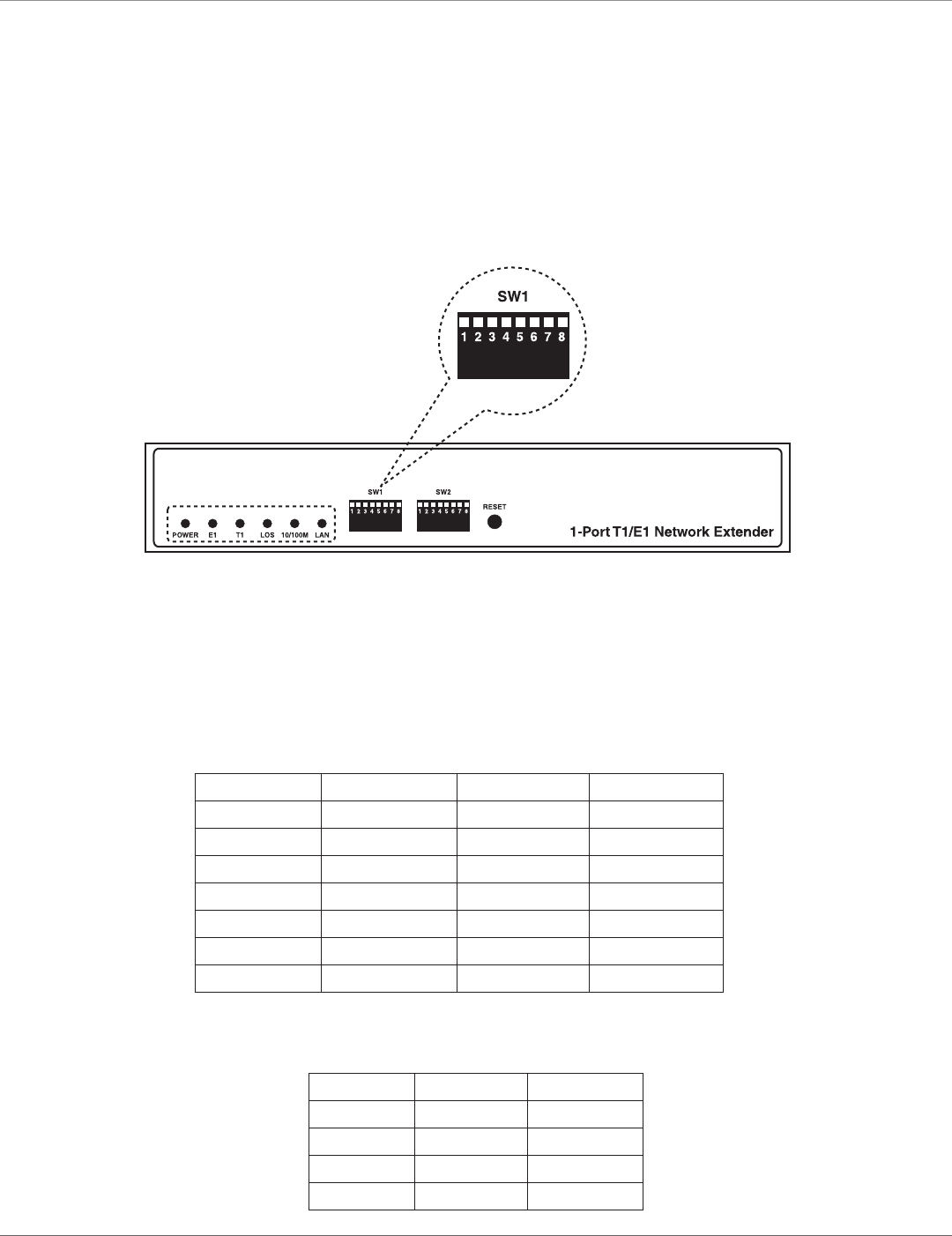
1. Select the Fractional E1/ T1 interface configurations via SW1-1–SW1-7 DIP switches. The default setup is T1. The DIP
switches are on the front panel. Refer to Figure 3-1 and Table 3-1 to see the DIP switches’ locations and definitions.
Figure 3-1. SW1-1–SW1-7 DIP switches.
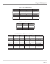
NOTE: Table 3-1 describes DIP switches SW1-1–SW1-7. Tables 3-2 through 3-5 describe these switches in more detail. Table 3-5
also describes DIP switch SW2-1.
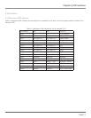
DIP Switches OFF ON Function
SW1-1 E1 T1 E1/ T1 selection
SW1-2 See Table 3-2 See Table 3-2 Impedance
SW1-3 See Table 3-3 See Table 3-3 Frame Mode
SW1-4 See Table 3-3 See Table 3-3 Frame Mode
SW1-5 See Table 3-4 See Table 3-4 Line Code
SW1-6 See Table 3-5 See Table 3-5 LBO
SW1-7 See Table 3-5 See Table 3-5 LBO
Table 3-1. SW1-1–SW1-7 DIP switches.
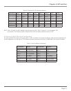
SW1-1 SW1-2 Impedance
OFF ON 75 ohm
OFF OFF 120 ohm
ON OFF 100 ohm
ON ON 100 ohm
Table 3-2. Impedance configuration.