


724-746-5500 | blackbox.com
Page 12
1-Port T1/E1 Ethernet Network Extender Kit
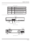
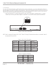
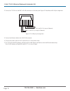
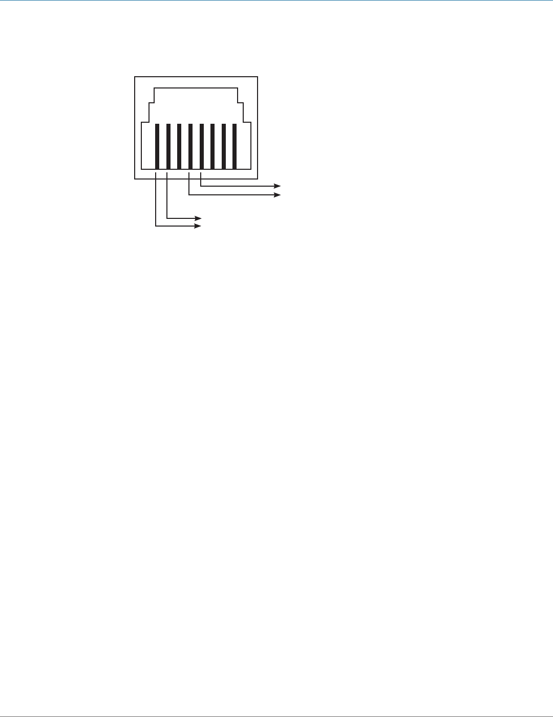
2. Connect the T1/E1 line to the BNC or RJ-48 connectors on the back panel. Figure 3-2 describes the RJ-48 pin assignment.
Pin 4 and Pin 5 (to input of demarc)
Pin 1 and Pin 2 (to output of demarc)
Figure 3-2. RJ-48 port pin assignment.
3. Connect the Ethernet cable to the RJ-45 LAN connector.
4. Connect the power cord to the AC outlet and turn on the power switch.
5. The T1/E1 and LAN LED indicators will light and the LAN indicator will flash to show the Ethernet data activity.
The LOS LED indicator will light RED when E1/T1 is in Loss of Signal.