


724-746-5500 | blackbox.com
Page 14
AC1132A
724-746-5500 | blackbox.com
Chapter 2: Overview
2.4 Hardware Description
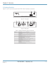
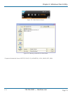
Figures 2-1 and 2-2 show the front panel of the AC1132A. Table 2-1 describes its components.
1 2
Figure 2-1. Front panel.
3 4 5 6 7 8 3
Figure 2-2. Back panel.
Table 2-1. Wireless Presentation System III components.
Number Component Description
1 USB connector Connects to mouse and/or keyboard
2 Power LED Lights when power to the unit is on
3 Antenna port Connects to antenna
4 5-VDC power connector Links to power
5 VGA connector Connects to projector input
6 Audio connector Attaches to audio
7 RJ-45 port Links to LAN
8 Reset button Press to reset the unit