


13
FIBER LINK
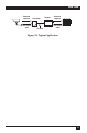
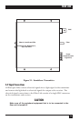
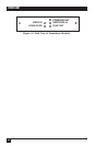
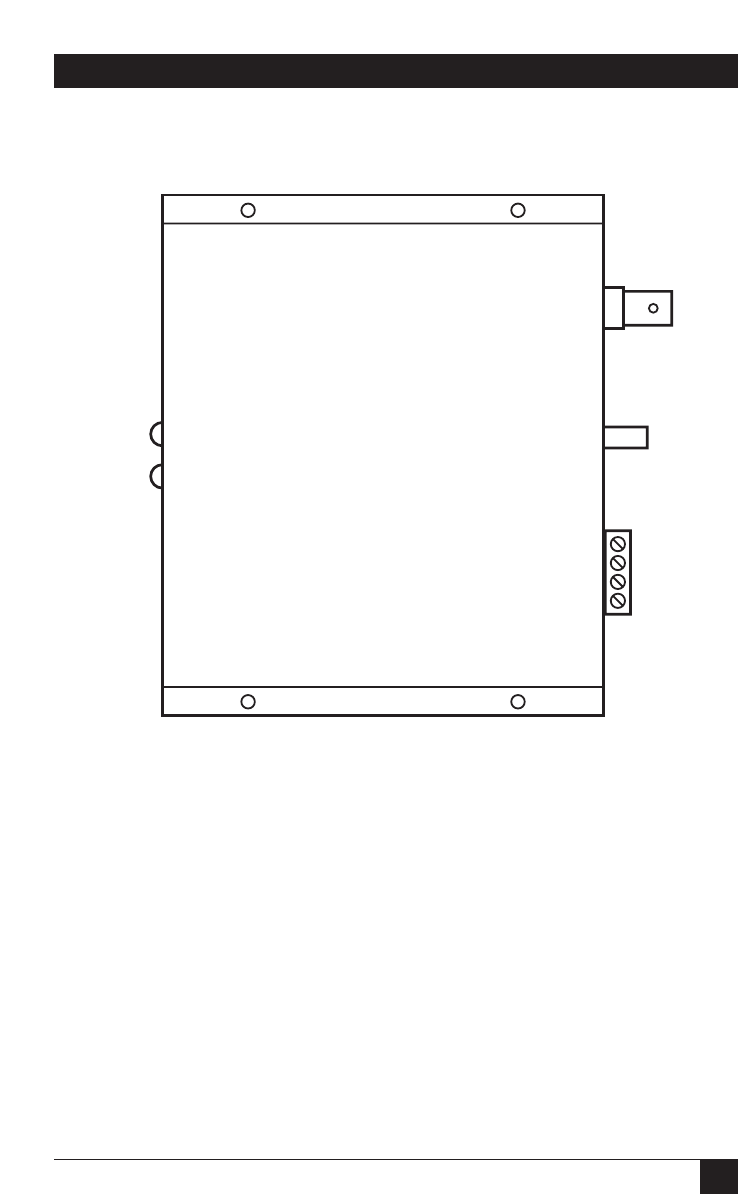
Figure 3-1. Standalone Transmitter.
3.2 Signal Connections
All fiberoptic links convert electrical signals into a light signal at the transmitter
and convert the light back to electrical signals for output at the receiver. The
electrical signal connections to the Fiber Link consist of a single BNC connector
on the transmitter and receiver.
CAUTION
Make sure all the peripheral equipment that is to be connected to the
fiber unit is turned off.
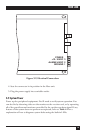
BNC
Fiber
Video In, Level/Loss LEDs
Command Out, Response In,
Sync Out LEDs
Power
connection (see
Figure 3-2)