


16
FIBER LINK
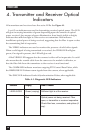
4. Transmitter and Receiver Optical
Indicators
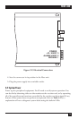
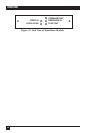
All transmitters and receivers have five active LEDs. See Figure 4-1.
Level/Loss indicators are used in determining received optical power. The LED
will glow in varying intensities of green depending upon the amount of optical
power received. Any amount of green illumination, from barely visible to bright,
indicates that sufficient light is a the receiver or transmitter. Red indicates
insufficient optical power is being received, suggesting that the fiber is open or that
the transmitting link is inoperative.
The VIDEO indicators are used to monitor the presence of valid video signals.
When a valid signal is being transmitted or received, the VIDEO LED will glow
green; if no signal is present, the LED will glow red.
A Red VIDEO LED suggests that the camera is either off or inoperative. It could
also mean that the coaxial cable from the camera to the module is defective, or
that the fiber link from the transmitter to the receiver is not functional.
The COMMAND indicator monitors outgoing PTZ Control Data Pulses, while
the RESPONSE LED shows return signals from the camera, when applicable.
The SYNC LED indicates Genlock Synchronization Pulses, when applicable.
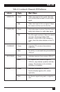
Table 4-1. Diagnostic LED Indicators
Indicator Display What It Means
LEVEL/LOSS Green (varying) Sufficient light is at the receiver.
Red Optical power not being received. Fiber
open, or transmitter or receiver inoperative.
Check fiber loss, connectors, and splices (if
any).