


10
SERVSWITCH
™
BRAND MATRIX VIDEO SWITCH
3. Installation
To set up your ServSwitch
™
Brand Matrix Video Switch system, take these steps:
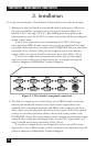
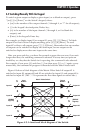
1. Making sure that the Switch is powered off, find its input ports. (These are
the top row of HD15 connectors on its rear panel, shown in Figure 3-1,
labeled “CPU 1” through “CPU 4”.) Run cabling from these ports to the
video-output ports of the PC CPUs or other devices that will be providing the
Switch’s video input.
If all of these input devices are transmitting VGA/SVGA/XGA-type
video signals on HD15 female connectors, you can use standard VGA video-
extension cables such as our product code EVNPS05-MM. Keep in mind that
the length of any of these cables plus the length of any of your monitor/
output cables (see step 2) should not be more more than 150 ft. (45 m).
If any of your input devices transmit some other type of video signal
and/or use some other type of video connector, you might need special
cables or adapters; call Black Box Technical Support.
Figure 3-1. The Switch’s rear-panel connectors.
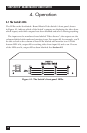
2. The Switch’s output ports are the bottom row of HD15 female connectors
labeled with numbered monitor icons. If all of your output devices are
standard VGA or multisync monitors with HD15 male connectors on their
video cables, you can plug them directly into these ports (if they’ll be placed
nearby) or run video-extension cables to them such as our product code
EVNPS05-MF (if they’ll be some distance away). Keep in mind that the length
of any of these cables plus the length of any of your CPU/input cables (see
step 1) should not be more more than 150 ft. (45 m).
If any of your output devices are designed to receive a non-VGA video
signal and/or use a different type of video connector, you might need special
cables or adapters; call Black Box Technical Support.