


ServSwitch Agility and Agility Dual
724-746-5500 | blackbox.com
Page 10
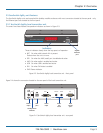
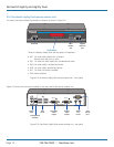
2.5.2 ServSwitch Agility remote receiver unit
The smart front faces feature the operation indicators as shown in Figure 2-5:
NET SER
AUD
USB DVI PWR
REMOTE
ServSwitch Agility
™
BLACK
BOXKVMoIP
EXTENDER
Gigabit
Ethernet
port
Indicators
These six indicators clearly show the key aspects of operation:
• NET Onwhenvalidnetworklinkispresent.
Flashes when the unit is in error.
• SER OnwhentheAUX(serial)portisenabledandactive.
• AUDOnwhenaudioisenabledandactive.
• USB OnwhenUSBisenabledandactive.
• DVI OnwhenDVIvideoisenabledandactive.
• PWR Powerindicator.
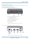
Figure 2-5. ServSwitch Agility remote receiver unit - front panel
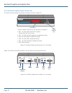
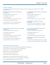
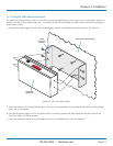
Figure 2-6 shows the connectors located on the rear panel of the remote receiver unit:
Figure 2-6. ServSwitch Agility remote receiver unit - rear panel
INDOOR
USE ONLY
OPTIONS
AUX
LINE IN/
LINE OUT
DVI-D
1 2
USER CONSOLE
5V
2.5A
ON
21
MIC IN
Video
output
Audio
line
in/out
AUX
(serial)
port
USB
ports
Configuration
switches
Power
input