


Express Ethernet Switch: LB9017A-R3
4
Table of Contents
About This Manual......................................................................................................................................................3
Preface ..........................................................................................................................................................................3
Table of Contents.........................................................................................................................................................4
Product Overview........................................................................................................................................................5
Front View.................................................................................................................................................................5
Figure 1: 16 Ports Web-based Smart Ethernet Switch ............................................................................................5
Package Contents.......................................................................................................................................................5
Product Features ........................................................................................................................................................6
Front Panel Display ...................................................................................................................................................7
Figure 3: Front Panel LEDs........................................................................................................................................7
Physical Ports ............................................................................................................................................................7
Understanding Front Panel Design........................................................................................................................7
Installation....................................................................................................................................................................8
Selecting a Site for the Equipment ............................................................................................................................8
Installation and Placement Instructions .....................................................................................................................9
Mounted to 19-inch standard rack .........................................................................................................................9
Desktop or any flat surface....................................................................................................................................9
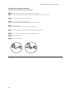
Optional Fiber Module Installation..........................................................................................................................10
Figure 4: Removal of cover plate Fiber module being installed ....................................................10
Connecting to Power ...............................................................................................................................................11
Figure 5: Rear view of the switch.............................................................................................................................11
Connecting to Your Network...................................................................................................................................11
Cabling ................................................................................................................................................................11
Network Segmentation ........................................................................................................................................12
Cable Specifications Table........................................................................................................................................12
Switch Configuration ................................................................................................................................................13
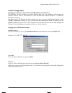
Setting up Console Port Connection (Web-Based Browser Interface) ....................................................................13
Logging on to The Ethernet Switch.........................................................................................................................13
Switch IP Address ...............................................................................................................................................13
User Name...........................................................................................................................................................13
Password..............................................................................................................................................................13
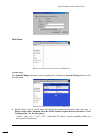
Main Menu ..............................................................................................................................................................14
System Change ....................................................................................................................................................14
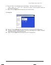
IP Configuration ..................................................................................................................................................15
Port ......................................................................................................................................................................16
VLAN..................................................................................................................................................................17
Trunking ..............................................................................................................................................................18
Save Configuration ..............................................................................................................................................19
Load Default........................................................................................................................................................20
Technical Specifications ............................................................................................................................................20
Physical Specifications ..............................................................................................................................................21
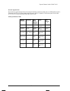
Connector Pinouts .....................................................................................................................................................22
Figure 6: RJ-45 Connector and Cable Pins.............................................................................................................22
Connector Pin-Out ....................................................................................................................................................22
Ordering Information ...............................................................................................................................................23