


12
2-PORT RS-232/422/485 PCI HOST ADAPTER
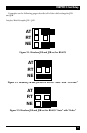
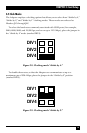
Figure 3-4. Headers J1B and J2B set for RS-485 “RTS” with “No Echo.”
Figure 3-5. Headers J1B and J2B set for RS-485 “RTS” with “Echo.”
3.2 Address and IRQ selection
The Adapter is automatically assigned I/O addresses and IRQs by your
motherboard BIOS. Only the I/O address may be modified by the user.
Adding or removing other hardware may change the assignment of I/O
addresses and IRQs.
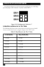
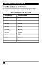
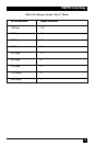
3.3 Line Termination
Typically, each end of the RS-485 bus must have line terminating resistors
(RS-422 terminates at the receive end only). A 120-ohm resistor is across each
RS-530/422/485 input in addition to a 1K ohm pull-up/pull-down combination
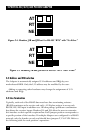
that biases the receiver inputs. Headers J1A and J2A allow the user to customize
this interface to their specific requirements. Each jumper position corresponds to
a specific portion of the interface. If multiple Adapters are configured in a RS-485
network, only the boards on each end should have jumpers T, P & P ON. Refer to
the following table for each position’s operation:
AT
RT
NE
AT
RT
NE